
TM 10-3930-641-20
(Sheet 1 of 2)
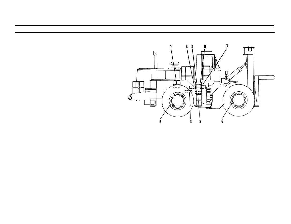
BRAKE SYSTEM DESCRIPTION
Brake system consists of:
Hydraulic pump (small section)
1.
Accumulator charging valve
2.
Accumulator
3.
Brake control valve
4.
Transmission neutralizer control valve
5.
Service brakes
6.
Emergency and parking brake
7.
Emergency and parking brake control valve
8.
HYDRAULIC PUMP (Smaller Section). Positive displacement,
1.
gear-type. Pump driven by the engine, supplies oil to operate
brake and implement pilot oil systems. Oil is pumped from
4.
BRAKE CONTROL VALVE. Regulates amount of high
hydraulic tank to accumulator charging valve for distribution
pressure oil from the accumulator required to obtain a specific
to the two systems.
pressure at the wheel brakes. Specific-pressure required is
determined by position of either brake pedal.
ACCUMULATOR CHARGING VALVE. Distributes flow of oil,
2.
from pump, to brake and implement pilot control systems. Con-
5.
TRANSMISSION NEUTRALIZER CONTROL VALVE. Causes
tains a check valve and a pressure relief valve. Check valve keeps
transmission to shift into neutral when left brake pedal is pushed.
pressure in accumulator in a constant range of 1950 PSI (137.1
This provides for full engine power to hydraulic system.
kg/cm 2) maximum to 1450 PSI (101.9 kg/cm2) minimum.
Pressure relief valve controls maximum oil pressure in accumu-
SERVICE BRAKES (4). Oil activated, disc-type. Pushing either
6.
later if accumulator charging valve malfunctions.
brake pedal sends pressurized oil from brake control valve to
push against discs and plates in the brake housing, causing fric-
ACCUMULATOR. A cylinder which stores pressurized hydraulic
3.
tion. This friction causes wheels to turn slower or stop.
oil for brake system. A part in accumulator allows oil to go to
TA 098566
brake control valve when either brake pedal is pushed.
Go on to Sheet 2

