
TM 10-3930-641-20
(Sheet 1 of 2)
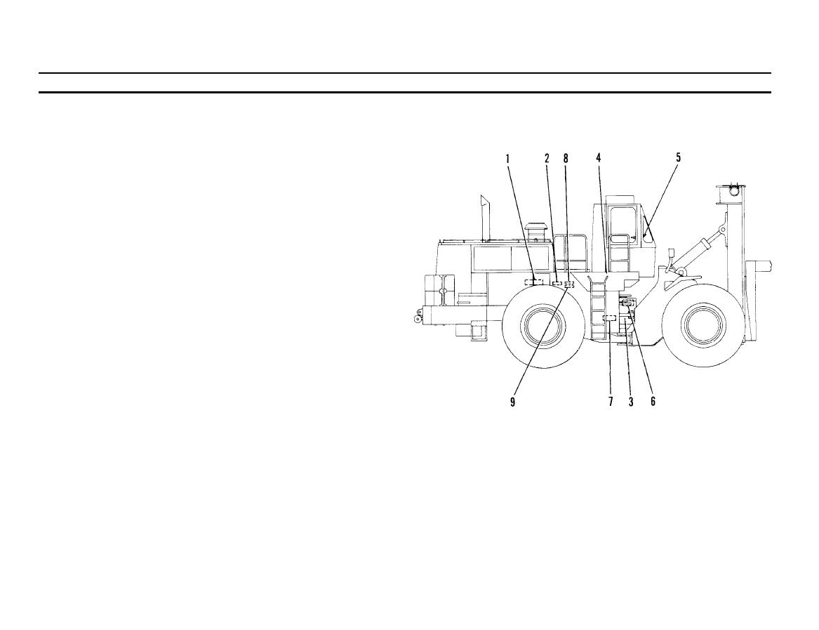
STEERING SYSTEM DESCRIPTION
Steering system can be divided into three groups: steering group, pilot
group, and supplemental steering group.
A.
STEERING GROUP COMPONENTS
HYDRAULIC PUMP (Larger Section). A gear-type, driven by
1.
the engine. The pump is used to supply hydraulic oil to the
steering system. The oil is pulled from the hydraulic tank and
pumped to the diverter valve.
9
STEERING CONTROL VALVE. Directs the high pressure oil to
-.
one of the two steering cylinders depending on which direction
the steering wheel is turned. The control valve is hydraulically
activated by the neutralizer valves.
STEERING CYLINDERS (2). Are activated by high pressure
3.
hydraulic oil from the control valve. When a left turn is being
made, the right steering cylinder is activated; when a right turn is
being made, the left cylinder is activated.
4.
HYDRAULIC TANK. The storage reservoir for all of the
hydraulic oil used in the machine except for the transmission
and torque converter. An inlet strainer provides filtering when
adding or replacing oil to the tank. Also, a filter is built into
the tank for filtering all of the oil returning from the hydraulic
system.
NEUTRALIZER VALVES (2) Stop the flow of pilot oil to the
6.
STEERING WHEEL AND COLUMN. Adjustable to eight differ-
5.
steering control valve at the end of a complete turn in either
ent positions. Seven of the positions are for operator comfort,
direction. This stops the steering action before the machine turns
while the eighth and most forward is for storing and locking the
against the frame stops. The valves are normally open, allowing
wheel when not in use. Pushing the wheel into the store position
flow through them.
also moves the transmission control lever to NEUTRAL.
TA 098585
Go on to Sheet 2

