
TM 10-3930-641-34-1
GOVERNOR REMOVAL AND INSTALLATION (CONT)
(Sheet 2 of 4)
LOCATION/ITEM
ACTION
REMARKS
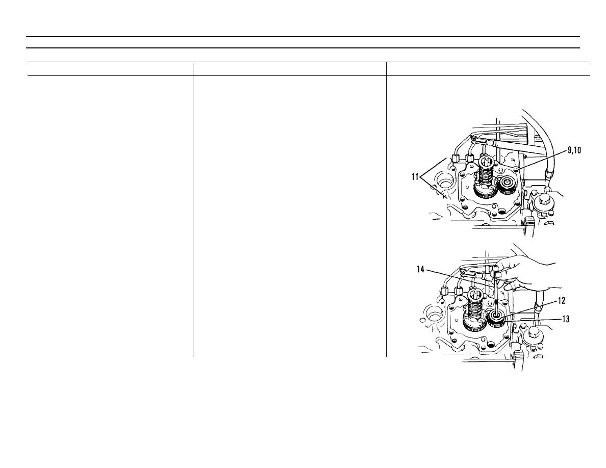
10. Fuel lines (11)
Disconnect from governor plate (10).
11. Capscrews (9) and governor plate
Remove.
(10)
INSTALLATION
CAUTION
Drive assembly must be removed from governor
plate for correct alignment before governor
plate is installed. Drive assembly can be dam-
aged if it is installed when governor plate is not
aligned with drive pinion assembly.
1. Gasket
Install on injection pump housing.
2. Governor plate (10) and capscrews
a. Install on fuel pump housing.
(9)
b. Be sure pins are aligned.
c. Install fuel lines (11).
NOTE
Racks must be held against rack stop pin and
governor lever engaged in groove in left hand
rack.
3. Stop (12)
a. Install in gear (13).
b. Make sure wide space in stop (12) aligns
with wide space on drive pinion.
TA099013
Go on to Sheet 4
3-81

