
TM 10-3930-641-34-2
HYDRAULIC (STEERING AND BRAKE) PUMP DISASSEMBLY/ASSEMBLY (CONT)
(Sheet 9 of 10)
LOCATION/ITEM
ACTION
REMARKS
19.
Isolation plate (35)
Install on inlet side of pump body (38).
20.
Back-up ring (30)
Install.
21.
Packing (31)
Install.
22.
Ring retainer (29)
Install.
NOTE
Radius of ring retainer (9) must be toward
bottom of pump body.
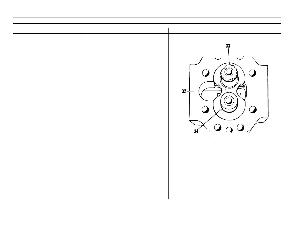
23.
Pressure plate (32)Put in position.
NOTE
Install pressure plate with bronze side toward
gears. Machined notch (trap slot) must be
toward outlet side of pump.
24.
Drive gear (33)Install in pump body.
NOTE
Outlet side of pump body facing away. Drive
gear goes in left side.
25.
Idler gear (34)
Install.
26.
Isolation plate (32)
Install.
27.
Back-up ring (30)
Install in pump body.
TA098979
Go on to Sheet 10
6-69

