
TM 10-3930-675-24-1
OVERLOAD PROTECTION TROUBLESHOOTING - CONTINUED
0011 00
Table 3. Error Code 132 - Boom Angle Sensor or Circuit Failure Troubleshooting Procedures.
MALFUNCTION
TEST OR INSPECTION
CORRECTIVE ACTION
Error Code 132 - Boom Angle Sensor or Circuit 1. Look under the rear of the Replace damaged boom angle
Failure.
boom and check the boom sensor (WP 0099 00).
angle sensor for damage and
proper mounting.
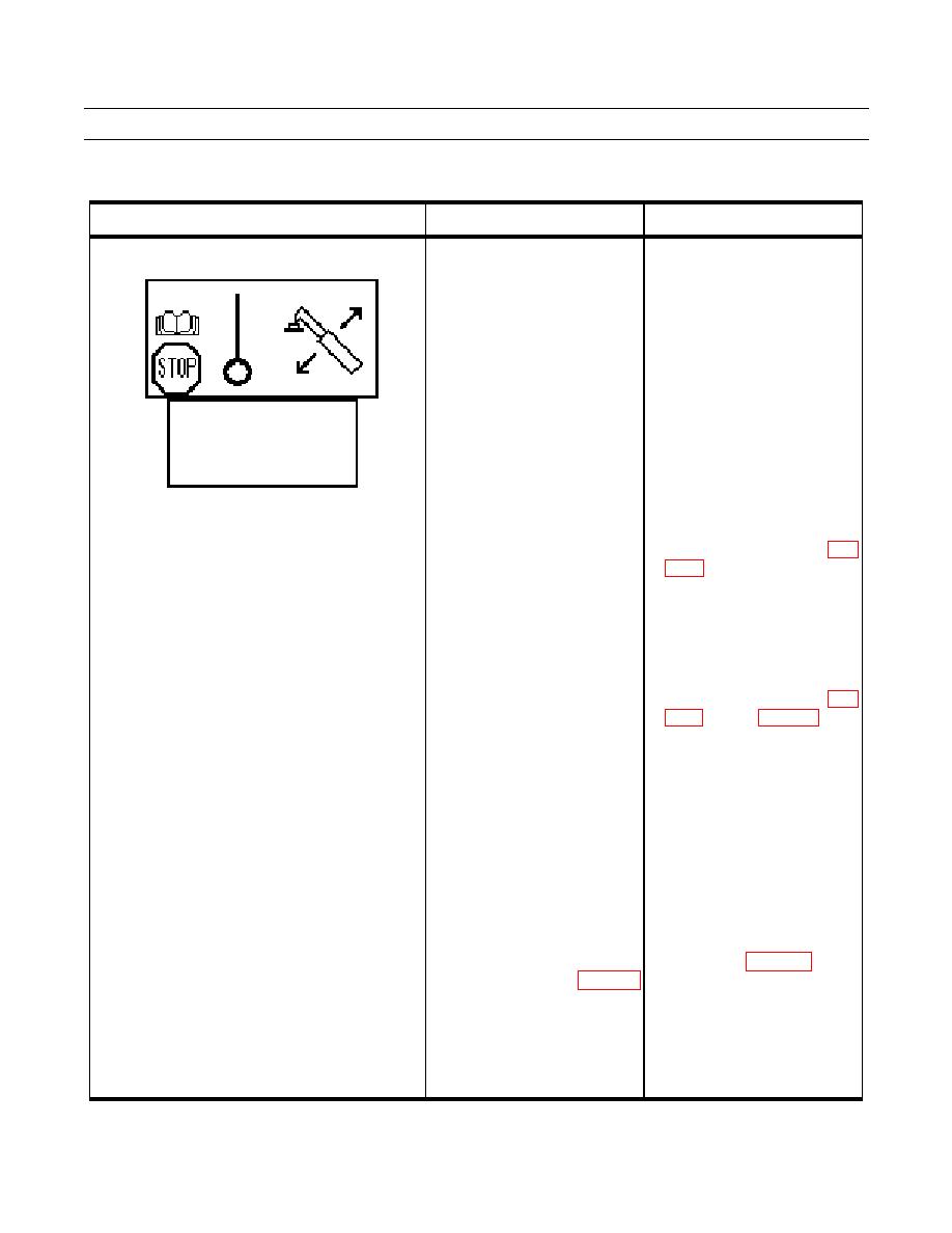
DIAG SERVO
1(13)
SYSTEM POWER
24.00V
POWER RI CAN
24.00V
POWER LE CAN
24.00V
10V REF OUT
10.00V
2. Enter "DIAG SERVO 7(13) in a. If no voltage (8V) is found,
the diagnostic menu and check
check voltage (10V) at X157
angle sensor voltage. The
between pins 2 and 3 (WP
voltage should be around 8V
0048 00-9).
with the boom fully lowered. b. If no voltage (10V) is found at
X157 between pins 2 and 3,
check continuity of wires
A15514A,
A15514B,
A15514C,
A15513D,
A15513C,
A15513B,
A15513A, and A1571 (WP
c. Repair or replace damaged
wires or connectors (WP 0113
00).
3. Inspect ECU (790) connector 1 a. Repair or replace damaged
pins 16, 26, and 27 and
wires or connectors (WP 0113
connector for damage.
00).
b. Replace damaged ECU (790)
(WP 0080 00).
4. Check voltage (10V) at X169 a. If no voltage (10V) is found at
between pins 2 and 3 and
X169 between pins 2 and 3,
voltage (8V) (boom fully
check continuity of wires BK,
lowered between pins 3 and 4
RD and BU (WP 0048 00-9).
with the ignition ON (WP 0048 b. If no voltage (8V) is found,
00-9).
replace boom angle sensor
(WP 0099 00).
c. Replace damaged or open
harness (WP 0113 00).
0011 00-4

