
TM 10-3930-675-24-2
BRAKE LIGHT AND PRESSURE SWITCHES REPLACEMENT - CONTINUED
0098 00
REMOVAL - CONTINUED
NOTE
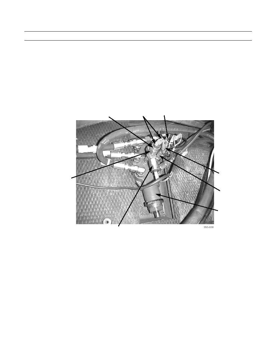
Tag connectors to ensure correct installation.
3.
Disconnect two connectors (8) of cab wiring harness from each of three switches (7).
4.
Remove each of four switches (7) from two fittings (9) of brake control valve (10).
5.
Remove two fittings (9) from brake control valve (10).
7
8
7
9
9
7
10
7
INSTALLATION
1.
Apply sealing compound to threads of two fittings (9).
2.
Install two fittings (9) on brake control valve (10).
3.
Install four switches (7) on two fittings (9).
4.
Connect two connectors (8) of cab wiring harness to each of three switches (7).
5.
Install right lower panel (6) with three screws (4) and three washers (5).
6.
Install left lower panel (3) with three screws (1) and three washers (2).
END OF WORK PACKAGE
0098 00-3/(0098 00-4 Blank)

