
TM 10-3930-675-24-2
TRANSMISSION ASSEMBLY REPLACEMENT - CONTINUED
0224 00
REMOVAL - CONTINUED
10.
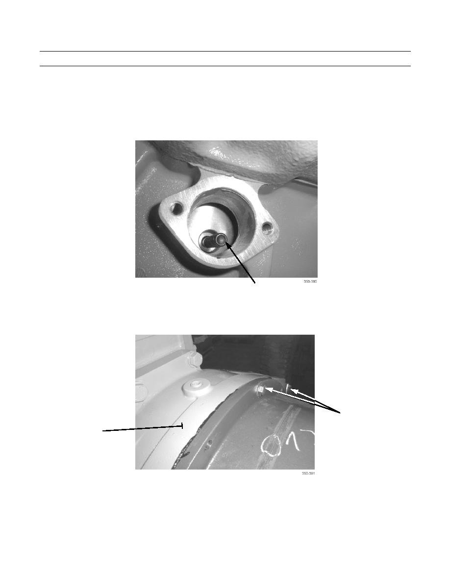
With assistance, bar engine in clockwise direction using accessory drive while observing through access hole. Stop rota-
tion when screw is visible through access hole.
11.
Remove screw (11) securing damper plates to flywheel.
12.
Repeat steps 10 and 11 to remove remaining eleven screws (11).
11
13.
Upon removal of last screw, insert guide stud and secure to damper plate.
14.
Remove 12 screws (12) and lockwashers (13) securing transmission to engine flywheel housing. Discard lockwashers.
12,13
FLYWHEEL
HOUSING
0224 00-7

