
TM 10-3930-675-24-2
HYDRAULIC SYSTEM VALVE MAINTENANCE - CONTINUED
0263 00
BOGIE/BOOM SUPPORT FLOW CONTROL VALVE REMOVAL
1.
Remove tiedown straps and clamps, as needed. Discard tiedown straps.
2.
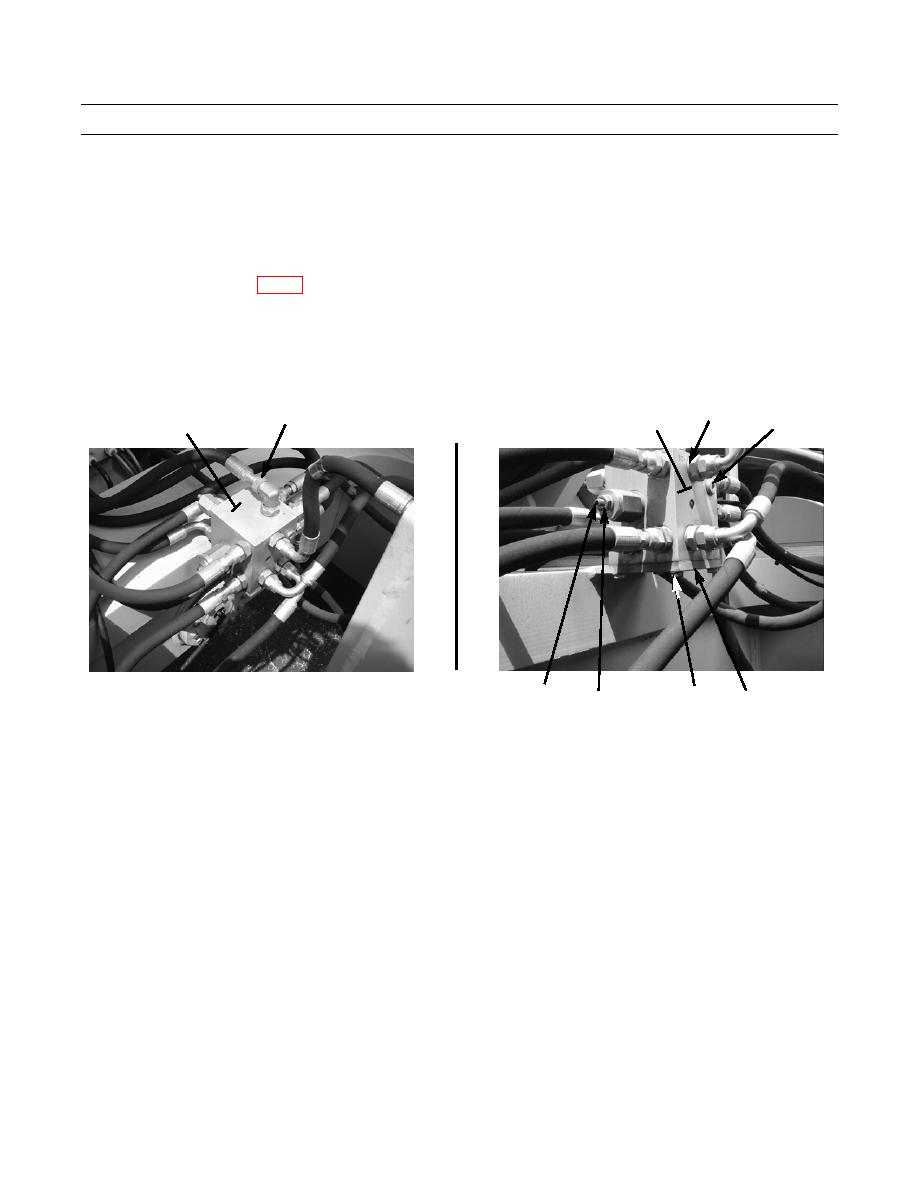
Remove 14 hoses (35) and O-rings (36) from valve (34). Discard O-rings.
NOTE
Refer to Foldout, FO-13 as a guide to remove hoses and fittings from valve or component.
Note position of tiedown straps and clamps to aid in installation.
3.
Remove four bolts (40), washers (41), and valve (34) from mounting plate (39).
4.
Remove 14 fittings (37) from valve (27).
37
35,36
34
34
38
434-40203
434-40202
43
40,41
42
39
BOGIE/BOOM SUPPORT FLOW CONTROL VALVE ADJUSTMENT
1.
Remove plug (38) and connect hydraulic pressure gauge to port "M" on valve (34).
2.
Place cab in transport position (TM 10-3930-675-10).
3.
Raise bogie wheel off of locking collar and turn 90 degrees, to UNLOCKED position (TM 10-3930-675-10).
4.
Lower bogie wheels to ground (TM 10-3930-675-10).
5.
Check bogie wheel tire pressure and adjust to 85 psi (586 kPa), if necessary (TM 10-3930-675-10).
6.
Loosen jamnut (42) on valve adjusting screw (43). Turn adjusting screw counterclockwise two turns.
7.
Start engine and open bogie pressure valve to apply pressure to valve (34) and bogie wheels (TM 10-3930-675-10).
8.
Turn adjusting screw (43) clockwise to increase pressure or counterclockwise to decrease pressure on hydraulic gage.
Adjust pressure to 1,088 psi (7,501.5 kPa) and tighten jamnut (42).
9.
Close bogie pressure valve and raise bogie wheels to stowed position. Turn bogie locking collar 90 degrees to LOCKED
position. Lower bogie wheels to seat locking collar on stowage flanges (TM 10-3930-675-10).
10.
Shut engine down and remove hydraulic gauge from valve (34). Reinstall plug (38) in port "M".
11.
Place cab in operational position (TM 10-3930-675-10).
0263 00-8

