
TM 10-3930-675-24-2
HYDRAULIC SYSTEM VALVE MAINTENANCE - CONTINUED
0263 00
COOLING FAN FLOW CONTROL VALVE (6037) REMOVAL
1.
Remove middle and rear radiator top grating sections (WP 0144 00).
2.
Remove radiator splash shield (WP 0143 00).
3.
Disconnect electrical lead from solenoid harness (124).
4.
Remove tiedown straps and clamps, as needed. Discard tiedown straps.
5.
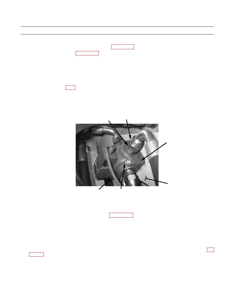
Remove four hoses (118) and O-rings (119) from valve (120). Discard O-rings.
NOTE
Refer to Foldout, FO-4 as a guide to remove hoses and fittings from valve or component.
Note position of tiedown straps and clamps to aid in installation.
6.
Remove two screws (122), washers (123), and valve (120) from mounting plate (121).
7.
Remove three fittings (117) from valve (120).
118,119
117
120
121
434-40214
122,123
124
COOLING FAN FLOW CONTROL VALVE (6037) INSTALLATION
NOTE
hydraulic hoses and applying proper torque.
Perform step 1 to install fittings removed from old valve, if new valve is being installed.
1.
Install four fittings (117) on valve (120).
2.
Lubricate and install four new O-rings (119).
3.
Install and tighten four hoses (118) on valve (120).
4.
Install valve (120) on mounting plate (121) with two screws (122) and washers (123). Tighten in accordance with WP
5.
Install clamps and new tiedown straps as needed, in same position as noted during removal.
6.
Connect electrical lead to solenoid harness (124).
7.
At hydraulic reservoir, open any ball valve that may have been closed.
0263 00-20

