
TM 10-3930-675-24-2
HYDRAULIC SYSTEM VALVE MAINTENANCE - CONTINUED
0263 00
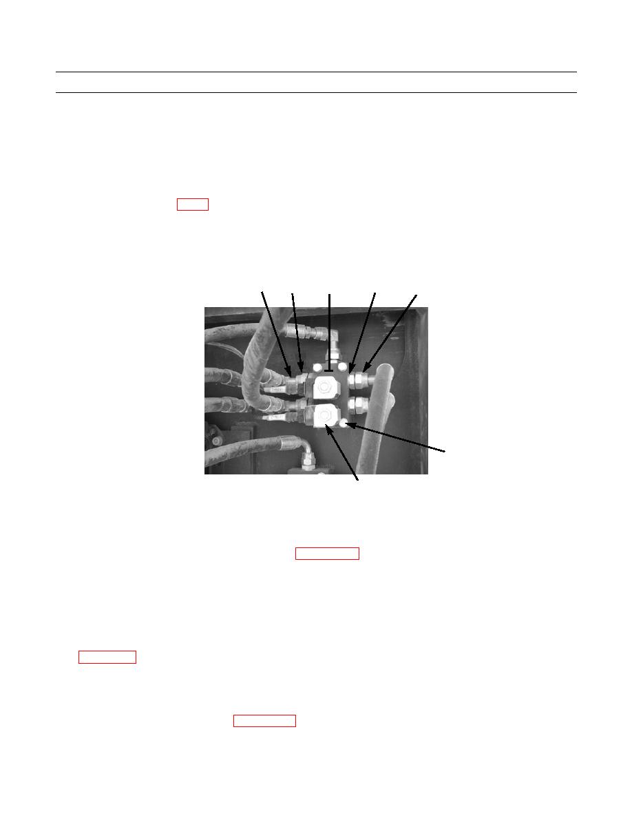
OSCILLATION FLOAT LOCK FLOW CONTROL VALVE REMOVAL
1.
Press in on retaining clip and disconnect electrical lead (156) from each of two solenoids (157).
2.
Remove tiedown straps and clamps, as needed. Discard tiedown straps.
3.
Remove five hoses (160) and O-rings (161) from valve (158). Discard O-rings.
NOTE
Refer to Foldout, FO-14 as a guide to remove hoses and fittings from valve or component.
Note position of tiedown straps and clamps to aid in installation.
4.
Remove four bolts (162), washers (163), and valve (158) from mounting plate (164).
5.
Remove four fittings (159) from valve (158).
157
159
156
160,161
158
162,163
434-40220
164
OSCILLATION FLOAT LOCK FLOW CONTROL VALVE INSTALLATION
NOTE
hydraulic hoses and applying proper torque.
Perform step 1 to install fittings removed from old valve, if new valve is being installed.
1.
Install four fittings (159) on valve (158).
2.
Lubricate and install five new O-rings (161).
3.
Install and tighten five hoses (160) on valve (158).
4.
Install valve (158) on mounting plate (164) with four bolts (162) and washers (163). Tighten bolts in accordance with
5.
Install clamps and new tiedown straps as needed, in same position as noted during removal.
6.
Connect electrical lead (156) to each of two valve solenoids (157).
7.
At hydraulic reservoir, open any ball valve that may have been closed.
8.
Check oil level in hydraulic reservoir (WP 0050 00).
9.
Start engine (TM 10-3930-675-10) and check for leaks.
0263 00-26

