
TM 10-3930-675-24-2
CAM FOLLOWER ASSEMBLY MAINTENANCE - CONTINUED
0275 00
REMOVAL - CONTINUED
5
1
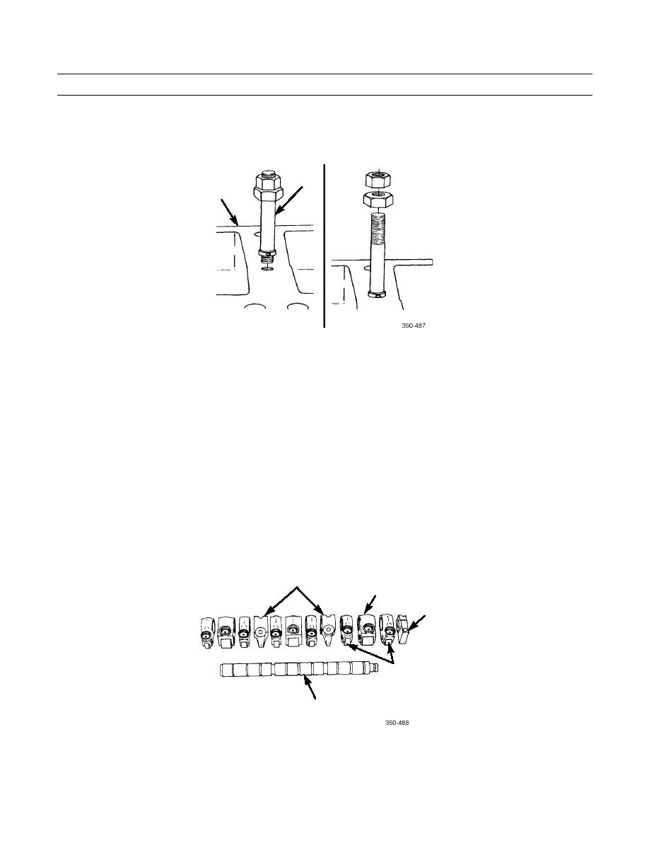
DISASSEMBLY
NOTE
Cam follower levers have established wear patterns and MUST be installed in the same position from
which they were removed.
1.
Mark end supports, internal supports, and all cam follower levers on front and rear sections to show location.
NOTE
Front and rear sections are disassembled and assembled in the same manner.
2.
Remove end support from shaft.
3.
Remove intake valve cam follower lever, injector cam follower lever, exhaust valve cam follower lever, and shaft sup-
ports from cam follower shaft.
4.
Repeat steps 2 and 3 to disassemble remaining section.
INJECTOR CAM
SHAFT SUPPORT
FOLLOWER LEVER
END
SUPPORT
VALVE CAM
FOLLOWER LEVER
CAM FOLLOWER
SHAFT
0275 00-3

