
TM 5-3810-306-34
WARNING
Compressed air used for cleaning
purposes will not exceed 30 psi. Use
only with effective chip guarding and
personal
protective
equipment
(goggles/ shield, gloves, etc.).
1. CLEAN ALL PARTS WITH SOLVENT P-D-680
AND BLOW DRY WITH COMPRESSED AIR.
2. VISUALLY
INSPECT
PUMP
GEROTOR DRIVE AND HOUSING FOR
6. MEASURE CLEARANCE OF
GEROTOR
DAMAGE, CHIPS, CRACKS OR EXCESSIVE
PLANETARY TO BODY BORE.
WEAR.
Max. clearance = .015 in. (.381 mm).
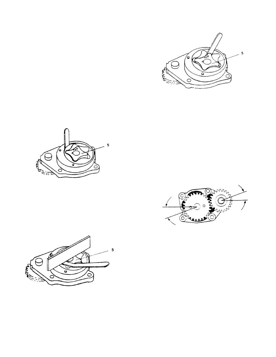
3. INSTALL
GEROTOR
PLANETARY
IN
ORIGINAL POSITION.
7. MEASURE GEAR BACKLASH. LIMIT (USED
PUMP) .003 TO .015 IN. (.08 TO .38 MM).
LIMIT (NEW PUMP) .003 TO .013 IN. (.08 TO
.33 MM).
NOTE
If
clearances
exceed
limits,
oil
pump
replacement is necessary.
4. MEASURE TIP CLEARANCE.
Max. clearance = .007 in.
(.1778 mm).
5. MEASURE CLEARANCE OF GEROTOR
DRIVE/ GEROTOR PLANETARY TO PORT
PLATE.
INSTALLATION:
1. INSTALL BACK PLATE (3) AND TAP LIGHTLY
WITH HAMMER UNTIL SEATED.
2. LUBRICATE LUBE PUMP (1) WITH CLEAN
ENGINE OIL.
3. INSTALL LUBE OIL PUMP (1).
a. Install lube pump (1) locating idler gear pin
(4) into locating bore in cylinder block.
Max. clearance = .005 in. (.127 mm).
4-60

