
TM 5-3810-306-34
Section III. HYDRAULIC CYLINDERS MAINTENANCE
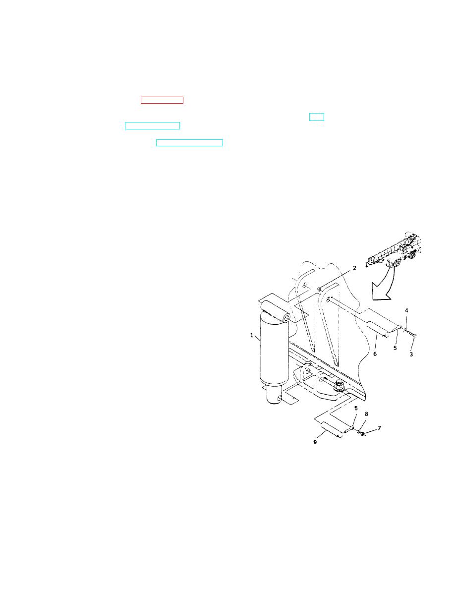
AXLE LOCKOUT CYLINDER INSTALLATION
TOOLS: General mechanic's tool kit: automotive (5180-00-177-7033)
SUPPLIES:
Cotter pins (Item 56, Appendix B)
EQUIPMENT CONDITIONS: Negative battery cable disconnected at shunt. (Refer to TM
5-3810-306-20.)
Hydraulic system shut down and pressure relieved from lines.
(Refer to TM 5-3810-306-20.)
b. Install new cotter pin (5) through hole in retaining
REMOVAL:
shaft (6) and secure to the stud with flatwasher
(8) and locknut (7).
1. REMOVE LOCKOUT CYLINDER (1).
c.
Rotate lockout cylinder up and position base end
a. Tag and disconnect two hydraulic lines from
of lockout cylinder between mounting gussets on
lockout cylinder (1). Cap or plug lines and
frame. Tap in retaining shaft (6).
openings.
b. Remove locknut (2), capscrew (3), flatwasher (4)
and cotter pin (5) securing retaining shaft (6) at
base end of lockout cylinder (1). Discard cotter
pin (5).
c.
Tap out retaining shaft (6). Swing lockout
cylinder out of mounting gusset.
NOTE
Lockout cylinder weighs 87 lbs (39.5
Kg).
d. Remove locknut (7), flatwasher (8) and cotter pin
(5) securing retaining shaft at rod end of lockout
cylinder. Discard cotter pin (5).
e. Tap out retaining shaft (9) and remove lockout
cylinder (1).
INSTALLATION:
1. INSTALL LOCKOUT CYLINDER (1).
a. Align rod end of lockout cylinder (1) between
mounting lugs on fifth wheel and tap in retaining
shaft (9).
13-86

