
TM 9-3950-253-13&P
0007
RETRIEVE LIFT FRAME - Continued
Release Locking Pins
CAUTION
Proceeding to Stage 2 without releasing locking pins may result in damage to equipment.
NOTE
Perform steps 1 through 4 for both sides of lift frame.
To relieve pressure on the locking pin, operator may have to press UP and DOWN
buttons on control panel to enable release of locking pin. Keep UP and DOWN
movements, when required, minimal.
1.
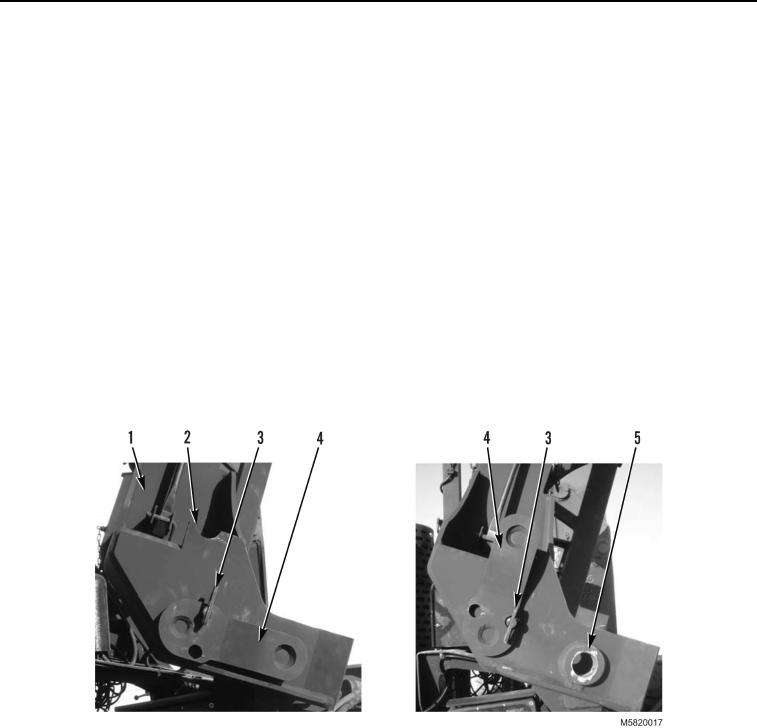
From left side of lift frame (Figure 7, Item 1), release lower locking pin anti-loose fastener (Figure 7, Item 3).
2.
Pull out lower locking pin (Figure 7, Item 4) from securing tube (Figure 7, Item 5) and rotate locking pin to
vertical position.
3.
Align locking pin (Figure 7, Item 4) with cradle (Figure 7, Item 2) on lift frame (Figure 7, Item 1) and push
locking pin toward lift frame.
4.
Lock anti-loose fastener (Figure 7, Item 3).
Figure 7. Secure Locking Pin.
03/15/2011Rel(1.10)root(opusualwp)wpno(O582007)

