TM 10-3930-675-20-1
0004 00-23
TROUBLESHOOTING INTRODUCTION - CONTINUED
0004 00
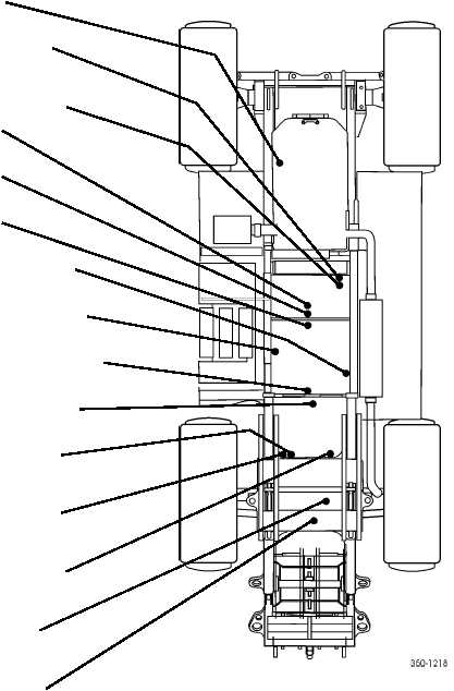
Figure 13. Hydraulic Component Location.
END OF WORK PACKAGE
Cooling Fan Hydraulic Pump
(Left Side of Engine)
Emergency Steering Pump
(Bottom Right-Rear of Transmission)
Boom and Brake System Hydraulic
Pump (Top Right-Rear of Transmission)
Tophandler Hydraulic Pump
Steering Hydraulic Pump #2
Steering Hydraulic Pump #1
Main Control Valve (On Right Frame Rail)
Steering Control Valve (On Left Frame Rail)
Servo Control Valve (On Frame Crossmember)
Auxiliary Pump (On Frame Crossmember)
Brake Accumulator Evacuation Valve -
Circuit #2 (Behind Cab)
Brake Accumulator Evacuation Valve -
Circuit #1 (Behind Cab)
Steering Accumulator Evacuation Valve
(Behind Cab)
Brake Charging Valve (Underneath
Frame Crossmember)
Over-Center Pressure Control Valve
(on Frame Crossmember)