TM 10-3930-675-24-1
EQUIPMENT DESCRIPTION AND DATA - CONTINUED
0002 00
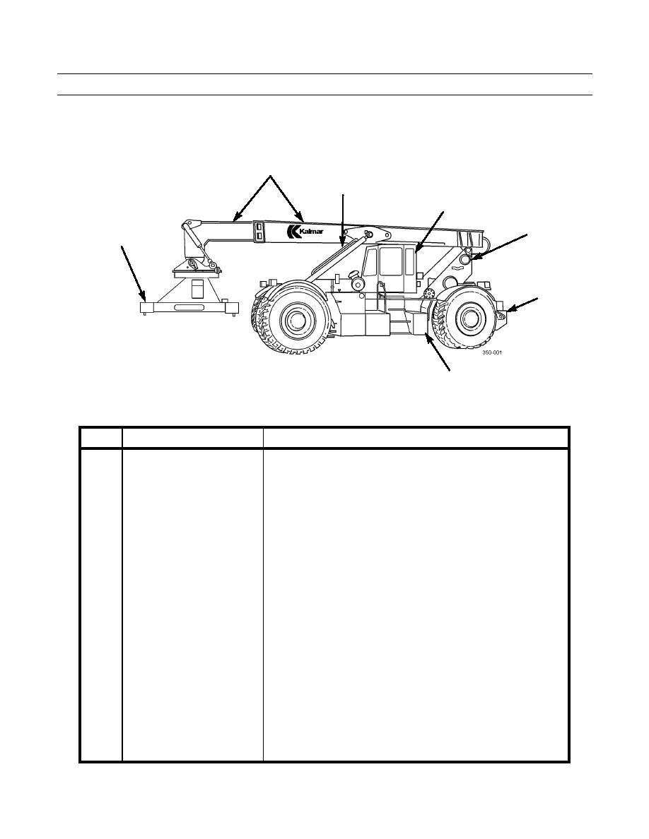
LOCATION AND DESCRIPTION OF MAJOR COMPONENTS
2
3
4
5
1
6
7
KEY
COMPONENT
DESCRIPTION
1
Tophandler
Electro-hydraulically operated 20 to 40 ft (6.10 to 12.19 m) tophandler.
Capable of sideshifting, rotation, forward/rear tilting, left/right tilting,
and load position leveling and locking. Also interfaces with forklift
attachment.
2
Boom Assembly
Electro-hydraulically operated heavy duty steel boom designed for
moving, lifting, and stacking 20 to 40 ft (6.10 to 12.19 m) ISO
containers.
3
Boom Lift Cylinders
Electro-hydraulically operated cylinders raise, lower, and support the
boom assembly.
4
Operator's Cab
Contains all driving and container handling controls as well as heating,
air conditioning, and filtered ventilation system controls. During air
transport operations, the cab is moved to the left side of the chassis,
then lowered and secured in place.
5
Boom Support
Rear support and pivot point for the boom to include an unlocking
device that allows the boom assembly to be lowered into the transport
position.
6
Frame
A heavy-duty steel construction with tie-downs, towing lugs, and
pintle hook.
7
Remote Hydraulic Control
Location of selected hydraulic remote controls. Also access to
Compartment
hydraulic system test and sampling ports.
0002 00-3


