TM 5-3810-306-34
INSTALLATION:
d. To make the measurements, turn on the heater
again and measure the increase in fuel volume
1. INSTALL FUEL (DOSING) PUMP (1).
for two 90 second periods. At the same time,
measure the electrical voltage at the control unit
a. If removed, position clamp (8) on mounting studs
terminals B3 (+) and C2 (-).
and secure with two new lockwashers (7) and
nuts (6).
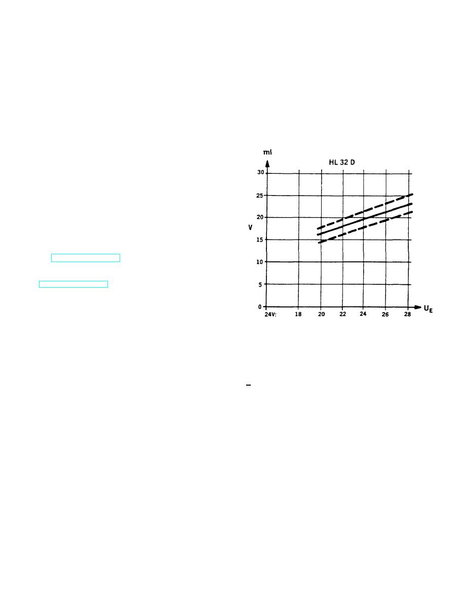
e. Take the data recorded in step d and apply it to
the following graph. The point of intersection
b. Slide bumper (9) and pump (1) into clamp (8)
must lie within the shaded area.
and tighten.
c. Slip hose (5) over fitting on pump and secure
with hose clamp (4).
d. Slip hose (3) over fitting on pump and secure
with hose clamp (2).
e. Connect electrical leads to pump and marked
during removal.
2. OPEN PETCOCK ON BOTTOM OF HEATER FUEL
TANK.
3. CONNECT GROUND CABLE AT SHUNT. (REFER
TO TM 5-3810-306-20.)
4. CHECK CAB HEATER OPERATION. (REFER TO
TM 5-3810-306-10.)
CHECKING PUMP FLOW RATE:
1. CHECK FLOW RATE AS FOLLOWS:
a. Remove wiring harness cap from top of heater
and disconnect glow plug.
Delivery volume V (ml) of the dosing pump after 180
seconds pumping time plotted against the input voltage
b. Detach the fuel line from the heater and place
U (V) at the electronic control unit. Temperature T= +20
the end of it in a measuring cylinder such as a
+2 (C).
100 ml graduated burette.
c. Turn on heater. After 90 seconds, the heater
automatically goes to fault lock-out with
subsequent repeat start. Repeat this procedure
until fuel emerges from fuel line.
12-9


