
TM 9-3990-260-14&P
9-12. A-FRAME ASSEMBLY REPLACEMENT (CONT).
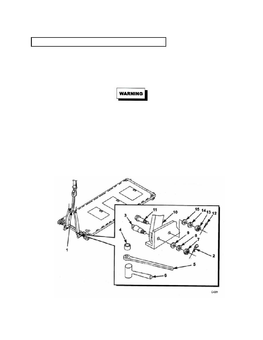
(3)
Remove hitch pins (2) from two front pins (3).
(4)
Remove 2-1/4" socket {4), socket wrench (5), and hammer (6), from PLS truck storage box
(refer to TM 9-2320-364-10).
(5)
Using 2-1/2" socket (4), socket wrench (5), and hammer (6), remove hex nuts (7), lock wash-
ers (8), washers (9), and front pins (3) from A-frame assembly (10). Discard lock washers.
The A-frame assembly must be securely held by the assistant to ensure it does not shift
after the last rear pin is removed. Failure to comply could result in injury to personnel.
(6)
Using assistant and lifting device, relieve pressure from rear pins (11).
NOTE
The removal of the rear pins may require shaking the A-frame or slight movement up or
down of the lifting device to relieve pressure enabling the rear pins to be removed.
(7) With the assistant holding the A-frame assembly (10) to prevent movement, remove two cot-
ter pins (12), two hex nuts (13), lock washers (14), washers (15), and rear pins (11). Discard
lock washers and cotter pins.
(8) Lift and remove the A-frame assembly (10) using the lifting device.
9-14
