
TM 10-3930-641-34-2
HAND METERING UNIT DISASSEMBLY/ASSEMBLY (CONT)
(Sheet 5 of 6 )
LOCATION/ITEM
ACTION
REMARKS
INSTALLATION
1.
Ball (19) and clip (18)
Install in body assembly.
2.
Hydraulic connection
Install in right port.
3.
Six springs (9)
Install in spool (13).
4.
Sleeve
Slide in position over spool (13).
5.
Pin (10) that holds spool (13) to
Install.
sleeve
6.
Sleeve and spool assembly
Install in body.
7.
Spacer (12)
Put in position on body.
8.
Drive assembly
Install in body.
9.
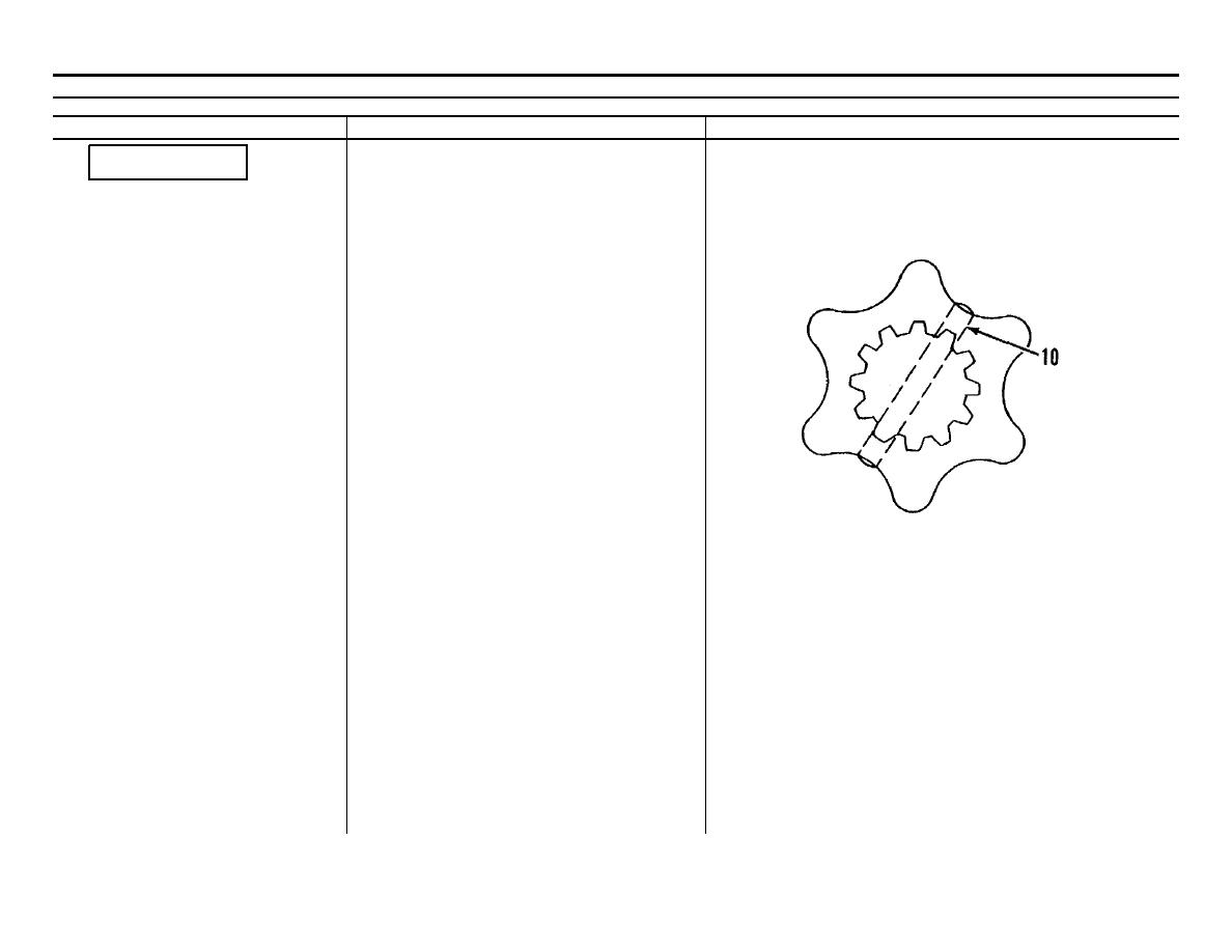
Gerotor assembly (15)
Install.
NOTE
Be sure gear in the gerotor assembly is alined
with pin (10) of sleeve assembly as shown.
TA172243
Go on to Sheet 6
6-22

