
TM 10-3930-675-24-1
TROUBLESHOOTING INTRODUCTION - CONTINUED
0004 00
ERROR CODE TROUBLESHOOTING - CONTINUED
(2)
Using left or right arrows on operator's control panel, scroll through operational screens, stopping at the
Kalmar maintenance icon (TM 10-3930-675-10). Press "Enter".
(3)
Enter access code "13221".
(4)
To select CALIBR SERVO menu, press "Enter". Use arrow keys to scroll through menu. Press "Enter" at
end of each menu to return to main menu.
(5)
Press right arrow key to scroll to additional CALIBR menus:
(a) CALIBR STEERING
(b) CALIBR GEARBOX (Transmission)
(6)
Use right or left arrow keys to scroll through each menu. Press "Enter" at end of menu to return to main
menu.
Initialization Menu, Access Code 32131 (Table 4). The initialization menu defines factory-set parameters for the
c.
RTCH. This is mostly an informational menu except for two of the menu screens. To access the Initialization
Menu:
(1)
Turn ON ignition switch, but do not start engine unless required to do so to accomplish the troubleshooting
procedure.
(2)
Using the left or right arrows on operator's control panel, scroll through operational screens, stopping at
the Kalmar maintenance icon (TM 10-3930-675-10). Press "Enter".
(3)
Enter access code "32131".
(4)
Use right or left arrow keys to scroll through initialization menu. Press "Enter" at end of menu to return to
main menu.
CAUTION
Do not change any of the values in screens 2(19) thru 17(19) for Army or 2(21) thru 17(21), 19(21),
20(21) for RESET/USMC. These are the factory-set parameters that regulate certain hydraulic func-
tions. Any changed values could result in degraded hydraulic operation.
(5)
Screen 1(19) for ARMY or 1(21) for RESET/USMC is used to set the units for the operator display
screen. Use the + or - key to change the value. Press "Enter" to save the change 0 = Metric and 1 = US.
(6)
Screen 18(19) for ARMY or 18(21) for RESET/USMC is used to activate information type error codes
that have been deactivated in the operator ECS display screens. Use the + or - key to change the value.
Press "Enter" to save the change. 0 = activated and 1 = deactivated.
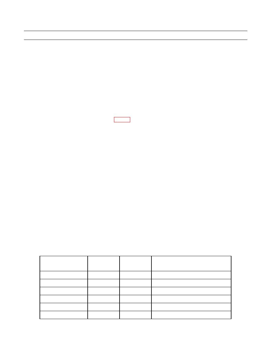
ECU
ECU
DIAGRAM
LOCATION
NAME
NUMBER
NUMBER
Hydraulic Servo
790
A34648.0200
Under driver's seat
Tophandler
791
A34652.0200
Forward end of boom
Steering System
792
A34651.0200
Inside cab behind right-rear panel
Transmission
793
A34650.0200
Inside cab behind right-rear panel
Engine
794
A34649.0200
Left side of engine
ECS Display Screen
795
A34647.0200
Driver's control panel
0004 00-4

