
TM 10-3930-675-24-2
CAB POSITION PROXIMITY SWITCHES REPLACEMENT - CONTINUED
0076 00
CAB SUPPORT-MOUNTED PROXIMITY SWITCH REMOVAL - CONTINUED
19
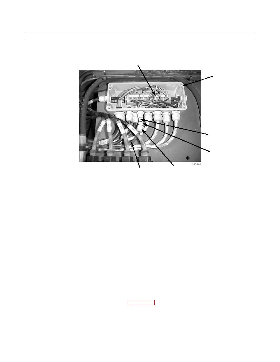
10
20
21
22
23
CAB SUPPORT-MOUNTED PROXIMITY SWITCH INSTALLATION
1.
Position proximity switch (12) on vehicle.
2.
Feed cable (23) through cable nut (22), grommet (21), and bushing (20) and into junction box (10).
3.
Using a jeweler's screwdriver, connect three wires of cable (23) to terminal blocks (19) of junction box (10).
4.
Install bushing (20), grommet (21), and cable nut (22) on junction box (10).
5.
Install cover (9) on junction box (10) and tighten four screws (8).
NOTE
Perform step 6 to install bracket to cab support.
6.
Install bracket (11) on cab support (18) with four washers (17), two screws (16), and new locknuts (15).
7.
Loosely install jamnut (14) on proximity switch (12).
8.
Position proximity switch (12) upward through bracket (11) and loosely install upper jamnut (13).
9.
Adjust two jamnuts (13 and 14) to position proximity switch (12) as noted during removal and tighten jamnuts. Correct
dimension is 1.20 in. (30 mm) from bracket to tip of sensor.
10.
Install new tiedown straps as needed.
11.
Install middle and rear transmission access covers (WP 0142 00).
12.
Return cab to operational position (TM 10-3930-675-10).
END OF WORK PACKAGE
0076 00-5/(0076 00-6 Blank)

