
TM 9-3990-260-14&P
5-7.
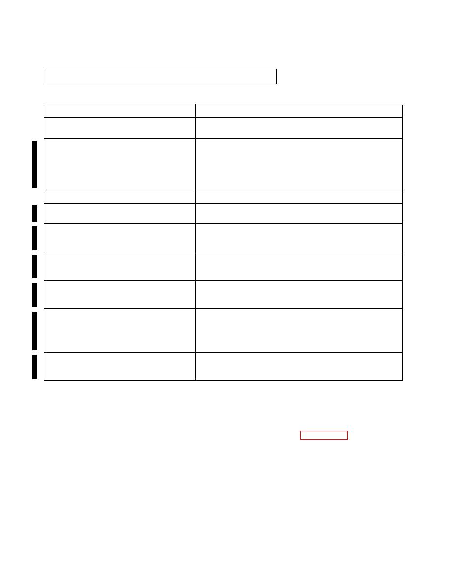
GENERAL WELDING MAINTENANCE (CONT).
Areas to be Inspected
Acceptable Crack Length Limits
1. Pin Blocks and Center Tube Welds and Less than 1/4 inch (6 mm)
Parent Material
2. Cross Beams
A crack should be repaired after it has reached 3/4 inch (19 mm).
The total length of cracks on a single crossmember should not
exceed 2 inches (51 mm). When cracks are present on several
crossmembers, action should be taken to repair them at the next
service. If a crossmember is completely missing, repairs should be
made prior to use.
3. Front and Rear Beams
Less than 1/4 inch (6 mm)
4. Main Beams (Note: Bends to bottom flange Cracks in the parent material or welds between the main beams
and main beams are normal.)
and cross beams cannot exceed 3/4 inch (19 mm).
5. Twistlocks
Due to the loads twistlocks can see during retrograde transport
mode, any cracks in the twistlock housing should be repaired
before reaching 3/4 inch (19 mm).
6. A-Frame
A crack should be repaired before it has reached 2 inches (5 cm).
The combined length of multiple cracks at any one location should
not exceed 4 inches (10 cm).
7. Hookbar (Welds securing the hookbar casting Cracks should be repaired prior to reaching 1 inch (2 cm) in
on the A-frame).
length. The combined length of multiple cracks at this location
should not exceed 1-1/2 inches (4 cm).
8. Multipurpose D-Rings
Due to the high loads that these fittings can see in transport mode,
any crack should be repaired before reaching 1/2 inch (1 cm) in
length. The combined length of multiple cracks at any one loca-
tion should not exceed 1/2 inch (1 cm). This applies to cracks
present in the adjoining structure also.
9. Decking
The maximum allowable single crack in the deck seams is 6
inches (15 cm) long. When multiple cracks are present, the com-
bined length of the cracks cannot exceed 10 inches (25 cm).
(1)
Acceptable Welding Patterns. Welding patterns conforming to the original manufacturer's
design are acceptable. Only abnormal welding patterns due to damage and/or improper
repair are cause for rejection. Inspection should be directed at looking for broken junc-
tures or welded repairs that are not consistent with other similar welds of the M3 CROP.
Preheating of parent material is required when welding the pin support plate, pin block,
bracing mechanism nut, and D-ring bar. For specifics, see paragraph 5-7, d. Crop Welding.
Acceptable Splicing. A splice is any repair of a primary structural member that replaces
(2)
material without complete replacement of the member. Areas repaired by straightening
and bead welding are not to be construed as splices. Gussets, backup plates or other
reinforcement (protector) plates are not to be construed as splices. An acceptable splice is a
minimum of 6 in. (15 cm) long and is a butt-welded insert. If a splice would end within
12 in. (30 cm) of another weld, it must be extended to that weld. An acceptable splice is
flush fitting and restores the original size and cross-sectional profile of the repaired com-
ponent. Backup plates installed on the backside of a splice are permissible if the backup
plate extends a minimum of 6 in. (15 cm) beyond each end of the splice.

