
TM 5-3810-306-34
c. Tag and disconnect lines from quick disconnect
couplers below hydraulic swivel.
d. To allow lines to pass through hydraulic swivel
barrel, tag and remove couplers from air and
hydraulic lines to air/transmission swivel.
CAUTION
When
removing
air/
transmission swivel, ensure
swivel is lifted vertically until
all rigid pipe extensions are
out of center of hydraulic
swivel.
e. Using an adequate lifting device, remove
air/transmission swivel, extension tubes and
hoses from hydraulic swivel.
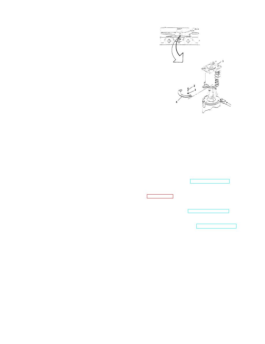
c. Place switch actuating cam (4) in place on swivel
casing and secure casing to hydraulic swivel
f. Remove hoses and extension tubes as required.
using six capscrews (2) and lockwashers (3).
INSTALLATION:
d. Install tagged couplers onto appropriate hoses.
Connect all couplers to tagged lines below
CAUTION
hydraulic swivel.
When
installing
air/
e. Install twelve air and oil lines to swivel barrel as
transmission swivel, ensure
tagged.
rigid pipe extensions are not
bent or crimped.
2. INSTALL AREA DEFINITION SWITCH
AND
ADJUST. (REFER TO TM 5-3810-30620.)
1. INSTALL AIR/TRANSMISSION SWIVEL.
3. INSTALL ELECTRICAL SWIVEL.
(REFER TO
a. Position swivel and connect tagged oil and air
lines to spool of the swivel.
4. CONNECT NEGATIVE BATTERY CABLE
AT
b. Insert swivel, extension tubes and hoses into
SHUNT. (REFER TO TM 5-3810-306-20.)
hydraulic swivel and install slotted arm into
keying lug on hydraulic swivel barrel.
5. START UP AIR SYSTEM. RETURN TO NORMAL
PRESSURE. (REFER TO TM 53810-306-10.)
6. START UP HYDRAULIC SYSTEM. RETURN TO
NORMAL PRESSURE. (REFER TO TM 53810-306-
10.)
7. REMOVE BLOCKING FROM LIFT CYLINDERS.
8. TEST FOR PROPER OPERATION AND INSPECT
FOR LEAKS.
END OF TASK
15-77
