
TM 10-3930-641-34-2
SUPPLEMENTAL STEERING PUMP DISASSEMBLY/ASSEMBLY (CONT)
(Sheet 4 of 5)
LOCATION/ITEM
ACTION
REMARKS
11.
Spacers (7) and retainers (5)
Remove.
12.
Retainers (8) and spacers (4)
Remove.
13.
Seals (6) and preformed packing (12)
Remove.
ASSEMBLY
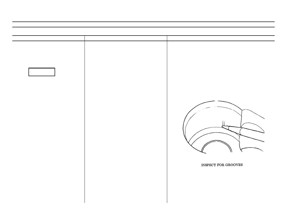
NOTE
Clean all parts.
If grooves in the bore are deeper than 0.015 in.
(0.381 mm), replace the body and gears.
1.
Seals (6) and preformed packing (12)
Assemble and install in bottom of housing.
2.
Spacers (7, 4) and retainers (5, 8)
Assemble around seals in bottom of housing.
3.
Pressure plate (9)
Install.
NOTE
Install pressure plate with machined notch
(trap slot) toward outlet side of pump and
bronze side toward the gears.
4.
Idler gear (11) and drive gear (10)
Install.
NOTE
Outlet side of pump body facing away. Drive
gear goes in left side.
5.
Pressure plate (9)
Install.
NOTE
Pressure plate must be installed with machined
TA 172241
notch (trap slot) toward outlet side of pump
Go on to Sheet 5
and bronze side toward gears.
6-77
