TM 10-3930-675-20-2
0167 00-4
TOPHANDLER HYDRAULIC SPREADER MOTOR REPLACEMENT - CONTINUED
0167 00
REMOVAL - CONTINUED
NOTE
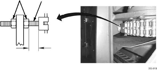
Prior to removal or disconnection of drive chain, measure and record length of adjuster rod as shown in loca-
tion diagram to ensure proper chain adjustment on installation.
5.
Measure and record chain adjuster as shown.
6.
Loosen chain adjuster jamnuts (9).
7.
Remove chain (15) from drive sprocket (14).
8.
Remove four socket head screws (13), hydraulic manifold (11) with hoses, and o-rings (12) from spreader motor (10).
Discard o-rings.
NOTE
Note direction of screws securing spreader motor to mounting weldment for installation.
9.
Remove ten screws (16), washers (18), and nuts (19) securing spreader motor (10) to mounting weldment (17).
WARNING
•
Use extreme caution when handling heavy parts. Provide adequate support and use assistance during
procedure. Ensure that any lifting device used is in good condition and of suitable load capacity. Keep
clear of heavy parts supported only by lifting device. Failure to follow this warning may result in death
or injury to personnel.
•
Spreader motor weighs approximately 150 lb (68 kg). Lifting device must have sufficient capacity to
lift motor. Failure to follow this warning may result in injury to personnel.
9
CHAIN
ADJUSTER
RECORD
MEASUREMENT