TM 10-3930-675-24-1
TROUBLESHOOTING PROCEDURES (NON-ERROR CODE) - CONTINUED
0007 00
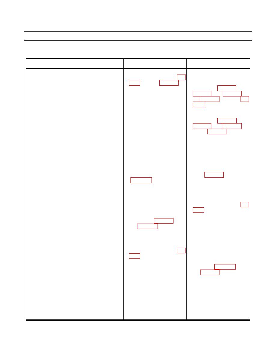
Table 2. Electrical Troubleshooting Procedures (Non-Error Code) - Continued.
MALFUNCTION
TEST OR INSPECTION
CORRECTIVE ACTION
24.Proximity Switches - Tophandler and Cab - 2. Check voltage (24V) at X195 a. If no voltage (24V) is found,
Continued.
between pins 7 and 9 (WP
check continuity of wires
A473, 473, A1743B, A1743C,
30) with the ignition on.
and A1957A (WP 0048 00-32,
USMC, check wires A475,
475, A174B1A, A174B1B,
and A1957A (WP 0048 00-18,
30, and WP 0048 00-32).
b. Repair or replace damaged
wires or connectors (WP 0113
00).
3. Move the cab to the transport a. If no voltage (24V) is found,
position (TM 10-3930-675-
check continuity of wires GY
10). Check voltage (24V) at
and RD in the X195 to X198
X198 between pins 1 and 3
cable (WP 0048 00-29).
ignition on.
(WP 0113 00).
4. Check voltage. With the a. If no voltage (24V) is found,
ignition on, activate the under
check continuity of wire OR in
cab proximity switch (7208)
the X195 to X198 cable (WP
with a piece of metal. Check
0048 00-14).
voltage (24V) between X195 b. If no LED indicator when
pin 5 and 7 (WP 0048 00-14
activated, replace proximity
and WP 0048 00-30). Check
switch (WP 0076 00).
LED indicator on the switch. c. Replace X195 to X198 cable
(WP 0113 00).
5. Check voltage (24V) at X175 a. If no voltage (24V) is found,
between pins 1 and 3 (WP
check continuity of wires
A1743D, A1957B, and for
on.
RESET or USMC, wire
A174B1C (WP 0048 00-29
and WP 0048 00-30).
b. Repair or replace damaged
wires or connectors (WP 0113
00).
0007 00-60


