TM 10-3930-675-24-1
BOOM IN/OUT TROUBLESHOOTING - CONTINUED
0041 00
Table 3. Error Code 160 - Extension Cylinder Boom IN
Control, Wiring Circuit Failure Troubleshooting Procedures.
MALFUNCTION
TEST OR INSPECTION
CORRECTIVE ACTION
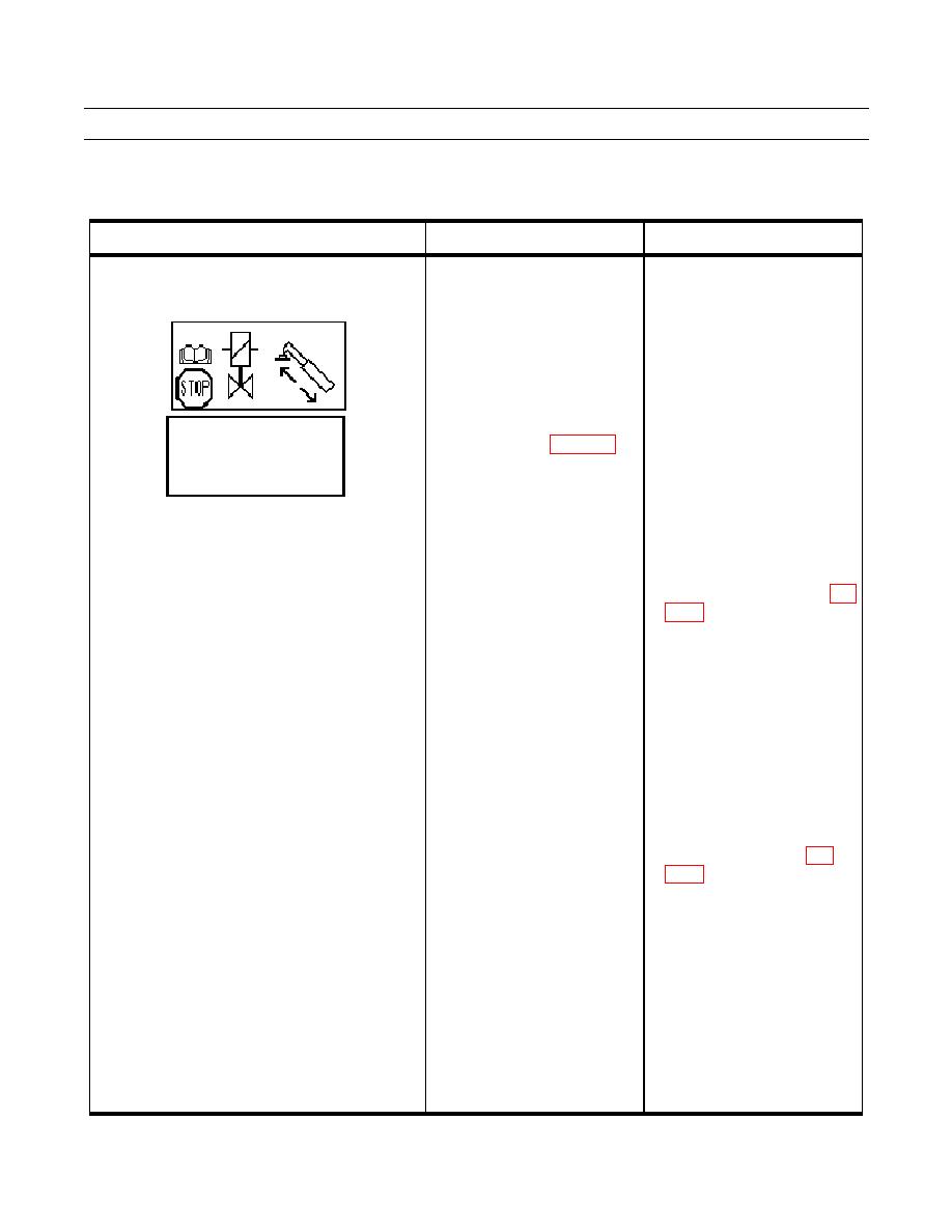
Error Code 160 - Extension Cylinder Boom IN 1. Enter "DIAG SERVO" 10(13) a. If no "OUTPUT" mA values
Control, Wiring Circuit Failure.
in the diagnostic menu and
display, perform
activate the boom in function.
troubleshooting steps for
BOOM IN "OUTPUT" and
ERROR CODE 127.
"INPUT" should have mA b. If no "INPUT" mA values
values during boom in
display, continue with step 2.
function.
2. Check voltage at X158 a. If voltage (16 to 24V) is found,
between pin 5 and pin 6 with
disconnect X158 and check
DIAG SERVO
10(13)
the ignition ON (WP 0048 00-
the resistance on the loose part
OUTPUT/INPUT
BOOM IN
0mA
0mA
8). Should be 0V with the
of X158 between pin 5 and pin
BOOM OUT 0mA
0mA
joystick in the neutral position
6. Resistance should be 23 to
and 6-16V during the boom IN
25 Ohms.
function.
b. If no voltage (6 to 16V) is
found, disconnect ECU (790)
connector 2 and check pin 12
for damage and check
continuity of wire A1586 (WP
0048 00-8).
c. Repair or replace damaged
wires or connectors (WP 0113
00).
d. Replace damaged ECU (790)
(WP 0080 00).
3. Move the cab to the transport a. If resistance (23 to 25 Ohms)
position (TM 10-39306-675-
is not as specified, replace
10). Remove the thin cover
servo control valve (WP 0250
plate just in front of the cab
00).
hose tray to gain access to the b. If specified resistance is
servo
Check
found, check continuity of
resistance of 6007 solenoid.
wires 1585 and 1586 (WP
Should be 23 to 25 Ohms.
0048 00-8).
Check solenoid for short to c. Notify Sustainment
ground.
Maintenance to replace
damaged open or shorted
harness.
d. Replace ECU (790) (WP 0080
00).
0041 00-3


