
TM 10-3930-675-24-2
INSTRUMENT PANEL SWITCHES, GAGES, AND PANEL LAMPS REPLACEMENT - CONTINUED
0073 00
12/24V CONNECTOR REMOVAL - CONTINUED
3.
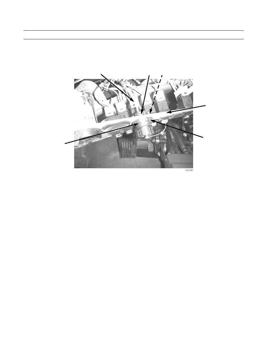
Loosen three screws (29) and disconnect three wires (28) from rear of 12/24V connector (32).
28
29
30
1
31
32
12/24V CONNECTOR INSTALLATION
1.
Thread three wires (28) through switch/gage panel (1).
2.
Connect three wires (28) to rear of 12/24V connector (32) and tighten three screws (29).
3.
Install 12/24V connector (32) on switch/gage panel (1) with two screws (31) and three nuts (30).
4.
Install switch/gage panel (1) on instrument panel (2) with ten screws (3).
END OF WORK PACKAGE
0073 00-9/(0073 00-10 Blank)
