
TM 10-3930-675-24-2
HYDRAULIC SYSTEM VALVE MAINTENANCE - CONTINUED
0263 00
BRAKE CHARGING VALVE REMOVAL
1.
Relieve pressure in both brake circuits by opening both brake drain shut-off valves (WP 0188 00).
2.
Remove tiedown straps and clamps, as needed. Discard tiedown straps.
3.
Remove five hoses (80) and O-rings (81) from valve (83). Discard O-rings.
NOTE
Refer to Foldout, FO-2 and FO-5 as a guide to remove hoses and fittings from valve or compo-
nent.
Note position of tiedown straps and clamps to aid in installation.
4.
Remove two bolts (84), washers (85), nuts (86), and valve (83) from mounting plate (82).
5.
Remove five fittings (79) from valve (83).
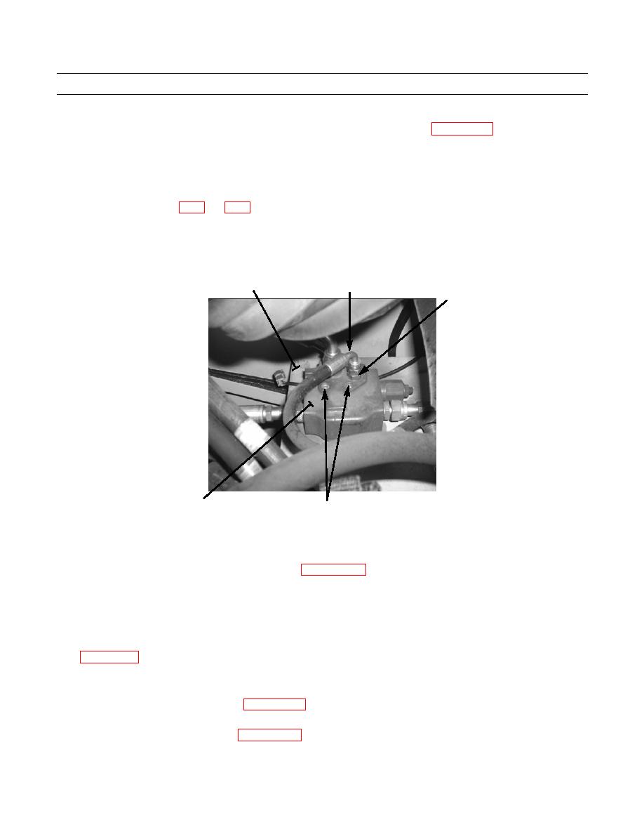
82
80,81
79
434-40209
83
84,85,86
BRAKE CHARGING VALVE INSTALLATION
NOTE
hydraulic hoses and applying proper torque.
Perform step 1 to install fittings removed from old valve, if new valve is being installed.
1.
Install five fittings (79) on valve (83).
2.
Lubricate and install five new O-rings (81).
3.
Install valve (83) on mounting plate (82) with two bolts (84), washers (85), and nuts (86). Tighten in accordance with
4.
Install and tighten five hoses (80) on valve (83).
5.
Install clamps and new tiedown straps as needed, in same position as noted during removal.
6.
Close both brake drain shut-off valves (WP 0188 00).
7.
At hydraulic reservoir, open any ball valve that may have been closed.
8.
Check oil level in hydraulic reservoir (WP 0050 00).
9.
Start engine (TM 10-3930-675-10) and check for leaks.
0263 00-15
