TM 5-3810-306-34
NOTE
The boom must be in the travel
position when checked.
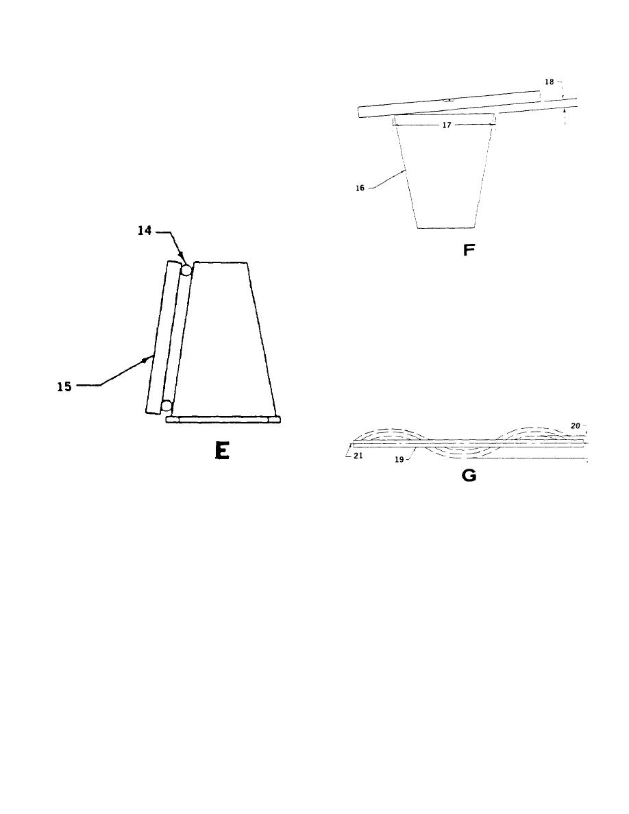
g. Check concavity and convexity by placing
straight edge over rods as shown in E.
Measure from straight edge to side plate
at mid-point, both sides. Record results.
Use straight edge and rods to check
lacings and top/bottom plates.
F.
CHECKING BOTTOM PLATE LONGITUDINAL
TWIST
16. FRONT OF SECTION
17. BOTTOM OF PLATE WIDTH
18. LONGITUDINAL TWIST
i. Check longitudinal waviness. Waviness
shall be smooth with positive/negative
arches (no kinks). Peak to peak waviness
shall be based upon peak to valley
dimensions as shown in G.
E. CHECKING CONCAVITY AND CONVEXITY
14. ROD
G. LONGITUDINAL
WAVINESS
(PEAK-TO-
15. STRAIGHTEDGE
VALLEY)
19. EDGE VIEW OF MEMBER
h. Position boom section with bottom plate
20. PEAK-TO-VALLEY MAXIMUM
facing up. Level rear end of section with
21. MEAN CENTER LINE
respect to bottom plate. Check front of
boom section to determine amount of
BOOM ALIGNMENT:
longitudinal twist in bottom plate as shown
in F.
CAUTION
NOTE
The following procedure involves the
side thrust pads in checking boom
When telescope section is not
width.
Avoid over adjusting the
twisted, vertical centerline of boom
thrust pads to a point where too
nose shall be located perpendicular
much binding exists between the
to center of bottom plate of section.
pads and the telescope section.
Boom damage can occur.
15-18


