TM 9-3950-253-13&P
0002
LOCATION AND DESCRIPTION OF MAJOR COMPONENTS
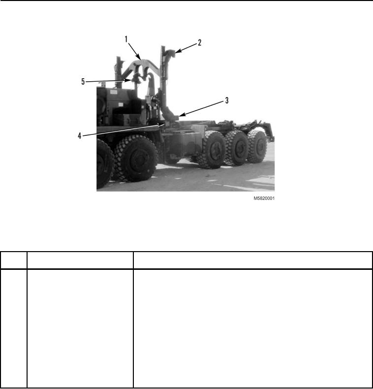
Figure 1. Left-Front View.
Table 1. Left-Front View.
KEY
COMPONENT
DESCRIPTION
1
Lift Frame
Attaches to ISO standard container for loading, transport, and
unloading container from vehicle.
2
Left Upper Lock
Engages with upper-left corner of ISO container. Locks lift frame to
container.
3
Left Lower Lock
Engages with lower-left corner of ISO container. Locks lift frame to
container and to stowage assembly when stowed on vehicle.
4
Stowage Control Panel
Container operator control buttons for operation of stowage unit.
5
Stowage Latch
Engages with bail bar on lift frame to secure lift frame to stowage
assembly.
03/15/2011Rel(1.10)root(descwp)wpno(G582002)

