
TM 9-3990-260-14&P
M3 CROP LOCATION AND DESCRIPTION OF MAJOR COMPONENTS.
a.
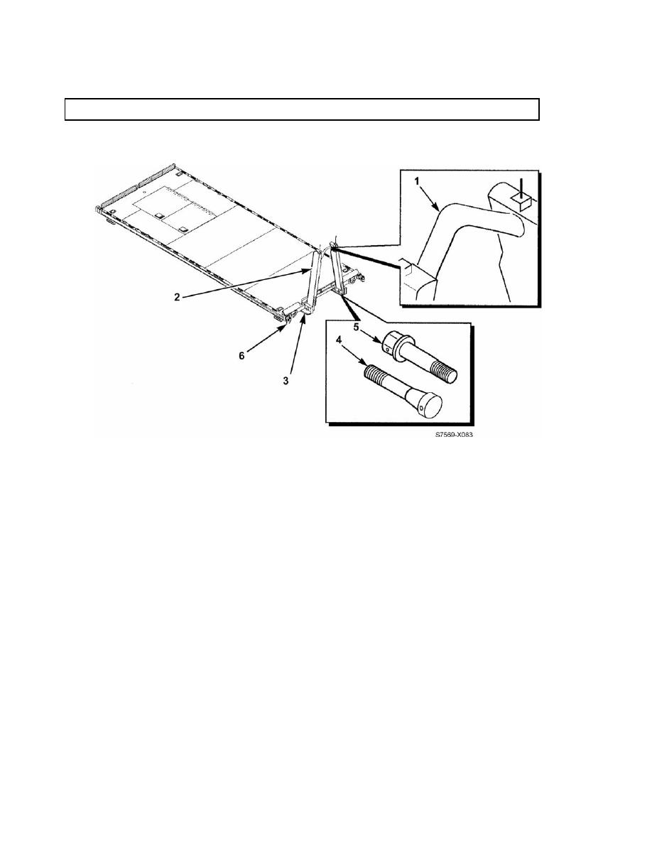
End Structure Assembly and Bail Bar. The bail bar (1) on the end structure assembly (2) of
the M3 CROP is used as a lifting point for the M3 CROP. The bail bar (1) couples with the LHS hook arm to lift
and pull the M3 CROP onto the PLS truck. The entire end structure assembly (2) can be lowered onto the M3
CROP deck to prepare the M3 CROP for unloaded stacking. When stacked, the end structure assembly (2) fits
inside the rails (3) of the M3 CROP above it, thus allowing M3 CROPs to be stacked vertically.
b.
Rails. The M3 CROP rails (3), located on the bottom of the M3 CROP, have dinlocks which mate
with locking plates on the PLS truck and trailer to secure the M3 CROP for road and rail operations.
c.
End Structure Assembly Hinge. Two tapered, threaded, front pins (4) with hex nuts, lock
washers, and two straight, threaded, rear pins (5) with hex nuts and lock washers are provided as an integral part of
the end structure assembly (2). The pins (4 and 5) are used to secure the end structure assembly (2) in the upright
position for normal use and allow the end structure assembly (2) to be folded in the horizontal position for stacking.
d.
Bracing Mechanisms. Bracing mechanisms (6) used to brace the M3 CROP inside an ISO con-
tainer are located at the two front corners. No further shoring is required to secure the M3 CROP inside an ISO
container.
