
TM 10-3930-641-34-2
ARTICULATED HITCH DISASSEMBLY/ASSEMBLY (CONT)
(Sheet 15 of 16)
LOCATION/ITEM
ACTION
REMARKS
42.
Spacer (24)
Install in lower pivot joint with bevel up.
43.
Pin (17)
Use jacks to align holes in bottom of pin with
holes in frame.
44.
Plate (26)
Put in position under rear of front main frame.
45.
Four capscrews (28)
Install.
46.
Plate (26)
Measure distance between plate and frame with
feeler gage. Remove plate and install same
thickness of shims.
47.
Plate (26) and four capscrews (28)
Install.
48.
Pin (17)
Turn with hydraulic jack until four holes are
aligned with holes in frame.
49.
Four capscrews (29)
Install.
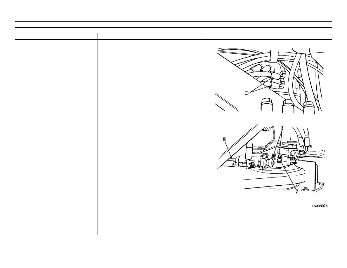
50.
Hydraulic line (E)
Connect to neutralizer valve.
51.
Eight hydraulic lines (D)
Connect to pilot control valve.
Go on to Sheet 16
6-50

