TM 10-3930-641-20
BRAKE PEDAL LINKAGES DISASSEMBLY/ASSEMBLY (CONT)
(Sheet 4 of 5)
LOCATION/ITEM
ACTION
REMARKS
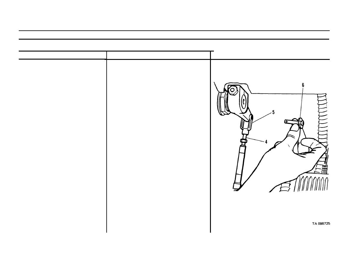
Disconnect from clevis (5).
6. Cable wire (4)
Lift up and lay access door down.
7. Access door assembly over brake
control valve group
Remove from clevis that secures cables to
8. Pins (6) and cotter pins
brake pedal levers.
Remove from valve group end of cable wire
9. Cable wire (4)
housing.
Remove.
10. Nuts (7) on upper cable housing (12)
11. Nuts (8) on middle cable housing (13) Remove.
12. Capscrew (9), washer, nut and clip
Remove.
(10)
13. Nuts (11) on lower cable housing (14)
Remove.
NOTE
If only cable wire needs replacing, then follow
Steps 1 thru 8, ASSEMBLY.
Go on to Sheet 5
2-356


