TM 10-3930-675-20-2
0082 00-1
ELECTRONIC JOYSTICK ASSEMBLY WIRING HARNESS REPLACEMENT
0082 00
THIS WORK PACKAGE COVERS
Removal, Installation
INITIAL SETUP
Tools and Special Tools
Tool kit, general mechanic’s (Item 31, WP 0204 00)
Materials/Parts
Strap, tiedown (Item 27, WP 0203 00)
Tag, marker (Item 28, WP 0203 00)
References
TM 10-3930-675-10
WP 0199 00
Equipment Condition
Master battery switch in OFF position
NOTE
Refer to wiring diagrams in WP 0199 00 and use marker tags, as necessary, to ensure proper connection of
connectors.
REMOVAL
1.
Raise joystick positioning lever and lift joystick assembly upward to free joystick assembly from seat (TM 10-3930-
675-10).
2.
Turn joystick housing (4) over for access to bottom of joystick housing.
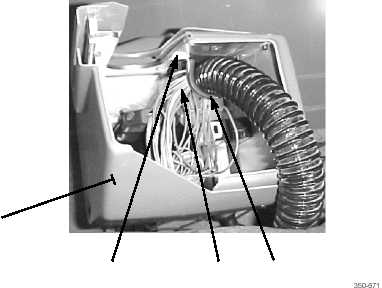
3.
Remove screw (3) and clamp (1) from protective cover of joystick wiring harness (2).
4
3
2
1