TM 10-3930-675-20-2
0127 00-2
BRAKE SYSTEM CHARGING VALVE PRESSURE ADJUSTMENT - CONTINUED
0127 00
ADJUSTMENT, BRAKE CIRCUIT NO. 1 - CONTINUED
WARNING
While adjusting brake charging valve, DO NOT remove adjusting screw from charging valve assembly. The
system is under pressure and failure to follow this warning may cause serious injury.
5.
Loosen adjusting screw jamnut (2) and slowly turn adjusting screw (1) until test gage indicates 1956-2538 psi (135-175
bar). Secure adjusting screw by tightening jamnut.
6.
Shut down engine.
7.
Relieve brake system hydraulic pressure by opening brake system evacuation valves (WP 0164 00).
8.
Disconnect test gage from hydraulic test point no. 1 (WP 0186 00).
9.
Close brake system evacuation valves (WP 0164 00).
ADJUSTMENT, BRAKE CIRCUIT NO. 2
1.
Relieve brake system hydraulic pressure by opening evacuation valves, then return valves to CLOSED position (WP
0164 00).
2.
Connect hydraulic pressure test gage to hydraulic test point no. 2 (WP 0186 00).
3.
Start engine (TM 10-3930-675-10).
4.
Test gage indicator will jump to pre-charged accumulator pressure of 1305 (90 bar), then slowly increase to system pres-
sure. If system pressure reaches 2900 psi (200 bar), OPEN evacuation valves (WP 0186 00).
WARNING
While adjusting brake charging valve, DO NOT remove adjusting screw from charging valve assembly. The
system is under pressure and failure to follow this warning may cause serious injury.
5.
Loosen adjusting screw jamnut (2) and slowly turn adjusting screw (1) until test gage indicates 1956-2538 psi (135-175
bar). Secure adjusting screw by tightening jamnut.
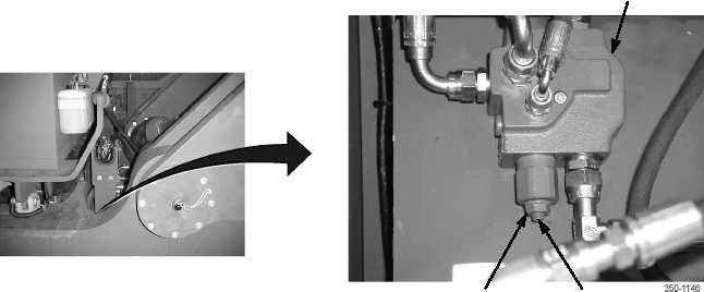
1
2
BRAKE CHARGING VALVE
(MOUNTED UNDER PLATE)