
TM 10-3930-675-24-1
OVERLOAD PROTECTION TROUBLESHOOTING - CONTINUED
0011 00
Table 5. Error Code 134 - Right Lift Cylinder Pressure Sensor or Circuit Failure Troubleshooting Procedures.
MALFUNCTION
TEST OR INSPECTION
CORRECTIVE ACTION
Error Code 134 - Right Lift Cylinder Pressure 1. Inspect the right lift cylinder a. Reconnect
disconnected
Sensor or Circuit Failure.
locking valve and pressure
sensor harness.
sensors for damage and b. Replace damaged pressure
connections.
sensor or harness (WP 0102
00).
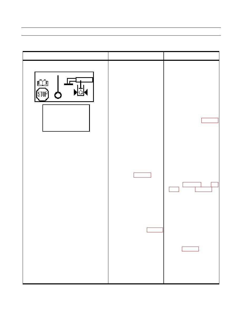
2. Enter "DIAG SERVO" 8(13) a. Check PRESS RI "PRESS"
in the diagnostic menu and
and "RETURN" voltages. If
check the pressure sensor
the "PRESS" voltage (3-6V) is
voltage. Lift the boom slightly
not found and "RETURN"
DIAG SERVO
1(13)
to pressurize the lift cylinders.
voltage is <2V, switch the
SYSTEM POWER
24.00V
The voltage should be 3 to 6V
pressure sensor harness leads
POWER RI CAN
24.00V
depending on boom position.
(768-1 and 768-3) (WP 0048
POWER LE CAN
24.00V
10V REF OUT
10.00V
00-9).
b. Recheck pressure voltages. If
the "RETURN" voltage (<2)
appears at "PRESS", replace
768-1 pressure sensor (WP
0102 00). Make sure to
switch the sensor leads back
after the test.
3. Check voltage (24V) at X159 a. If no voltage (24V) is found,
between pins 3 and 4 with the
check continuity of wires
ignition ON (WP 0048 00-9).
A1543D, A1543C, A15513C,
A15513B, A15513A, and
5).
b. Repair or replace damaged
wires or connectors (WP 0113
00).
4. Make sure the boom is slightly a. If no voltage (3 to 6V) is found,
raised. Check voltage (3 to 6V)
continue with step 5.
at X159 between pins 5 and 4 b. If voltage (3 to 6V) is found,
with the ignition ON (WP 0048
disconnect
ECU
(790)
00-9).
connector 1 and check pin 18
and connector for damage and
check continuity of wire
A1595 (WP 0048 00-9).
c. Repair or replace damaged
wires or connectors (WP 0113
00).
d. Replace damaged ECU (790)
(WP 0080 00).
0011 00-7
