TM 10-3930-675-24-1
OVERLOAD PROTECTION TROUBLESHOOTING - CONTINUED
0011 00
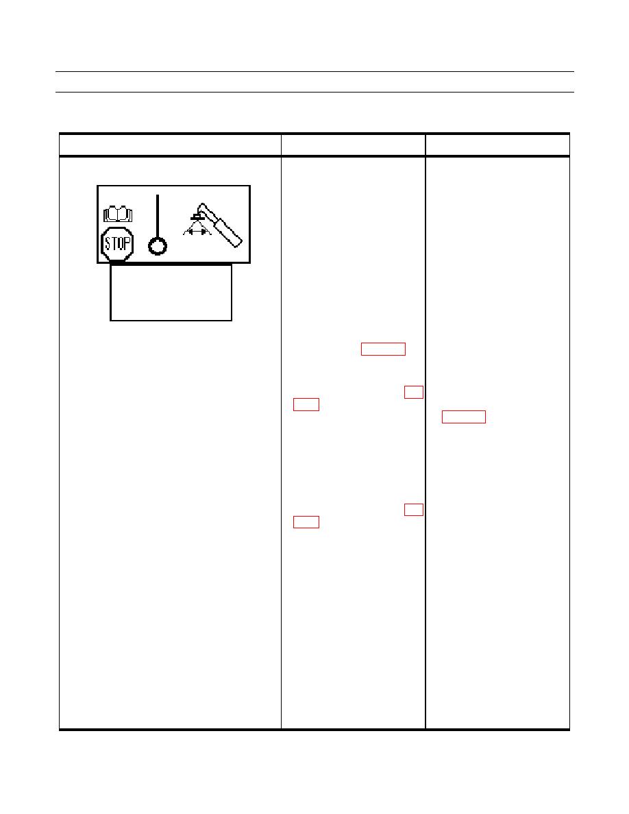
Table 8. Error Code 210 - Tophandler Angle Sensor or Circuit Failure Troubleshooting Procedures.
MALFUNCTION
TEST OR INSPECTION
CORRECTIVE ACTION
Error Code 210 - Tophandler Angle Sensor or 1. Inspect tophandler angle Tighten loose mounting bracket,
Circuit Failure.
sensor and lever and bracket replace damaged angle sensor or
for damage and secure mounting bracket (WP 0100 00).
mounting.
2. Enter "DIAG
Check lever "clocking" on angle
ATTACHMENT" 2(16) in the sensor (WP 0259 00).
diagnostic menu. Check tilt
angle voltage. With boom fully
lowered and tophandler level,
DIAG ATTACH 1(16)
voltage should be 4 to 6V.
SYSTEM POWER 24.00V
POWER RI CAN 24.00V
3. Remove the cover from the Repair damaged wires or
POWER LE CAN 24.00V
tophandler junction box to gain connectors (WP 0113 00
10 V REF OUT 10.00V
access. Check tilt angle sensor
cable connections at X180 pins
10, 11, and 12 (WP 0048 00-
26).
4. Check voltage (10V) at X180 a. If no voltage (10V) is found,
between pins 10 and 12 (WP
check continuity of wires
A18010, A1801, and A1802
ON.
(WP 0048 00-26).
b. Repair or replace damaged
wires or connectors (WP 0113
00).
c. Replace ECU (791) (WP 0080
00).
5. Check voltage at X180 a. If voltage is not as specified,
between pins 10 and 11 (WP
replace tilt angle sensor (WP
0100 00).
ON. Voltage should be 0.3 to b. If voltage is as specified,
9.5V, depending on tophandler
disconnect
ECU
(791)
tilt.
connector 1 and inspect ECU
and connector pins 9, 26, and
27 for damage.
c. Replace ECU (791) WP 0080
00.
0011 00-13


