TM 9-3950-253-13&P
0007
STOW LIFT FRAME - Continued
4.
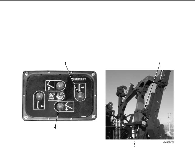
Stowage guide (Figure 40, Item 3) will be positioned under stowage rollers on lift frame (Figure 40, Item 2).
NOTE
Do not release DOWN button until hook arm stops.
Press UP and DOWN button as required to align locking plate with stowage
assembly.
5.
Press and hold DOWN button (Figure 40, Item 4). As soon as hook arm stops moving, release button.
Figure 40. Lift Frame Positioned on Stowage Guide.
NOTE
Perform steps 6 through 9 for both right and left sides.
6.
Release anti-loose fastener (Figure 41, Item 2) on lower locking plate (Figure 41, Item 1).
03/15/2011Rel(1.10)root(opusualwp)wpno(O582007)

