TM 9-3950-253-13&P
0070
TWISTLOCK SENSOR HARNESS INSTALLATION
NOTE
Perform step 1 for both right and left sides.
1.
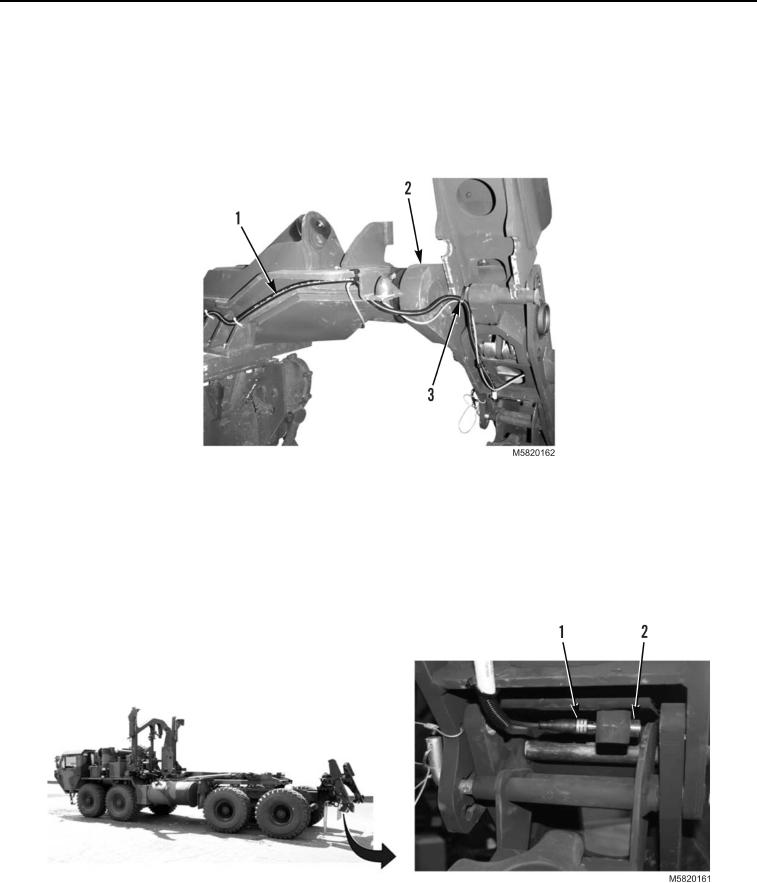
Route twistlock harness (Figure 27, Item 1) to slider assembly (Figure 27, Item 2), and install new tiedown
straps (Figure 27, Item 3) as required.
Figure 27. Twistlock Sensor Harness Installation.
NOTE
Perform step 2 for both right and left sides.
2.
Connect twistlock sensor harness (Figure 28, Item 1) to twistlock sensor (Figure 28, Item 2).
Figure 28. Twistlock Sensor Installation.
END OF TASK
03/15/2011Rel(1.10)root(maintwp)wpno(M582069)

