
TM 10-3930-641-34-2
DIFFERENTIAL AND BEVEL GEAR ASSEMBLY (CONT)
(Sheet 9 of 11)
LOCATION/ITEM
ACTION
REMARKS
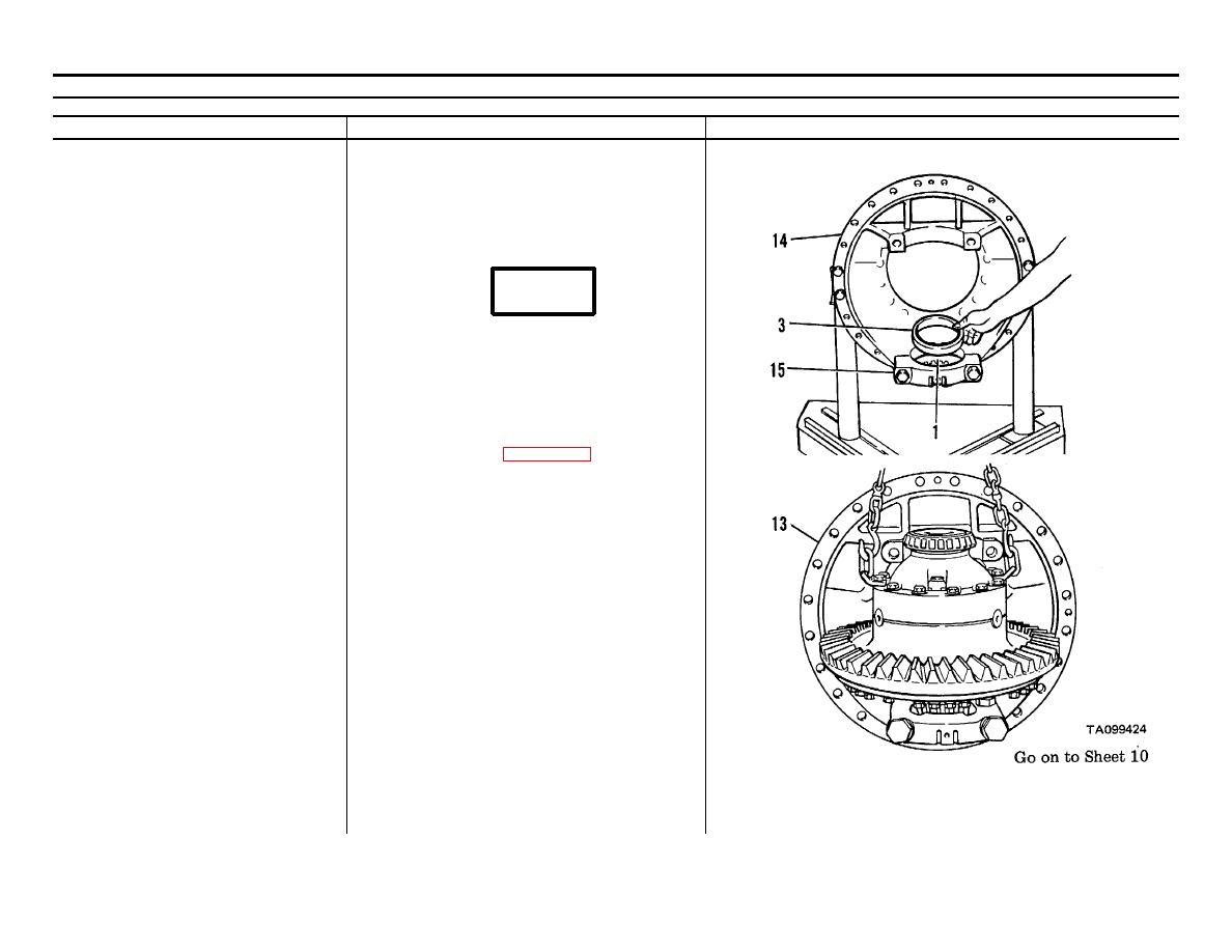
26.
Carrier assembly (14)
Position on repair stand as shown.
27. Bearing cap (15), adjusting ring (1)
Install.
and bearing cup (3)
CAUTION
Be sure cap is in correct position.
28.
Adjusting ring (1)
Turn ring clockwise five turns. That will
provide for initial bearing preload
adjustment. (See Differential and Bevel
Gear Adjustment, page 4-289.)
29.
Differential assembly
a. Attach hoist.
b. Position in carrier assembly (13) as shown.
NOTE
Be sure tapered roller bearing on differential
is properly seated in bearing cup attached to
carrier.
4-286
