TM 10-3930-675-20-2
0072 00-4
INSTRUMENT PANEL SWITCHES, GAGES, AND PANEL LAMPS
REPLACEMENT - CONTINUED
0072 00
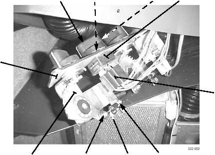
ROTARY SWITCH REMOVAL - CONTINUED
5.
Loosen setscrew (13) and remove knob (11) from switch (7) to be replaced.
6.
Remove nut (12) and switch (7) from switch plate (10).
NOTE
Perform step 7 for switches with electrical connectors.
7.
Disconnect connector(s) (14) of instrument panel wiring harness from rear of switch (7).
NOTE
Perform steps 8 and 9 for switches with control cables.
8.
Remove pushnut (17) and disconnect control cable (16) from rear of switch (18).
9.
Remove tiedown strap, lift tab of clip (15), and remove clip and control cable (16) from switch (18). Discard tiedown
strap.
ROTARY SWITCH INSTALLATION
NOTE
Perform steps 1 and 2 for switches with control cables.
1.
Install control cable (16) to switch (18) with clip (15) and install new tiedown strap.
2.
Connect control cable (16) to rear of switch (18) and install pushnut (17).
NOTE
Perform step 3 for switches with electrical connectors.
11
12
13
7
14
15
16
17
18
10