
TM 10-3930-675-24-2
CAB TRANSPORT LIFT MAINTENANCE - CONTINUED
0138 00
CAB TRANSPORT SYSTEM INSPECTION - CONTINUED
13.
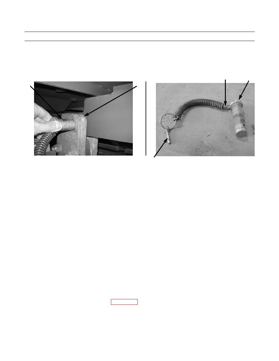
Inspect cab pins (11) and receptacles (12) for wear, damage, or rust. Clean pins and lightly lubricate with lubricating oil.
14.
Check for missing retaining pins (14) and attachment chains (13).
13
11
11
12
434-40107
434-40108
14
CAB TRANSPORT SYSTEM ADJUSTMENT
NOTE
Before performing any adjustment procedures, check clearances and alignment of cab pin recep-
tacles with the cab in both operational and transport positions. Check for pin alignment in the U-
shaped receptacles (at right side of cab, front, and rear) and at receptacles on cab left side.
A light source, a mirror, and a stiff wire approximately 3 ft (1 m) long with a 2-in. (5-cm) right
angle bend will aid in checking for clearances in hard to reach areas.
CAB ADJUSTMENT: OPERATIONAL POSITION
1.
Remove cab pins (11). Turn auxiliary pump on and move cab fully to operational position. Turn auxiliary pump off (TM
10-3930-675-10).
NOTE
Tag or mark shims, nuts, and washers to ensure the same order of replacement during installa-
tion.
Mark position of receptacle before loosening nuts.
Use one of the cab pins as a guide for aligning the two halves when tightening the bolts.
2.
Measure distance (A), between right-side cab wall and hydraulic mounting support. Starting point measurement should
be 4-9/16 1/8 in. (11.6 3.2 cm) as shown.
3.
Move cab to transport position (TM 10-3930-675-10).
4.
Remove front and rear access cover plates (WP 0142 00) to access right side cab pin receptacles.
5.
Loosen bolts (16), washers (17), and nuts (18) enough to adjust receptacles (15).
6.
Tighten bolts enough to allow for adjustment.
7.
Slowly move cab back to operational position, stopping at (A) (4-9/16-in. measured position).
0138 00-4
