
TM 10-3930-675-24-2
CYLINDER HEAD REPAIR - CONTINUED
0200 00
INSPECTION - CONTINUED
CAUTION
Support cylinder head in holding fixture to prevent damage to injector tip protruding from combus-
tion face.
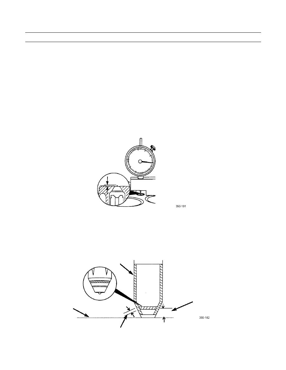
b.
Install injector into cylinder head without O-rings. Tighten to 55 lb-ft (75 Nm).
NOTE
If measurements in step c and d are not within limits, replace injector sleeve and O-ring.
c.
Turn cylinder head over and measure injector tip protrusion with depth gage.
(1)
Min. 0.090 in. (2.28 mm)
(2)
Max. 0.104 in. (2.65 mm)
FUEL INJECTOR TIP PROTRUSION
d.
Remove injector and measure bluing pattern. Bluing pattern for injector seating area must be approximately 0.50
in. (13 mm) from cylinder head combustion surface.
15.
Measure injector bore seating width. Width must be a minimum of 0.060 in. (1.52 mm)
INJECTOR
SLEEVE
INJECTOR
HEAD
SEATING AREA
SURFACE
INJECTOR BORE
SEATING WIDTH
0200 00-11
