TM 10-3930-675-24-2
FLYWHEEL ASSEMBLY REPLACEMENT - CONTINUED
0204 00
INSPECTION - CONTINUED
2.
Rotate flywheel, using engine barring tool, one revolution and record indication. Total indicator reading MUST NOT
exceed 0.0050 in. (0.127 mm).
NOTE
Flywheel face runout check results in five readings. If any one of the readings exceeds the maximum,
flywheel must be replaced.
3.
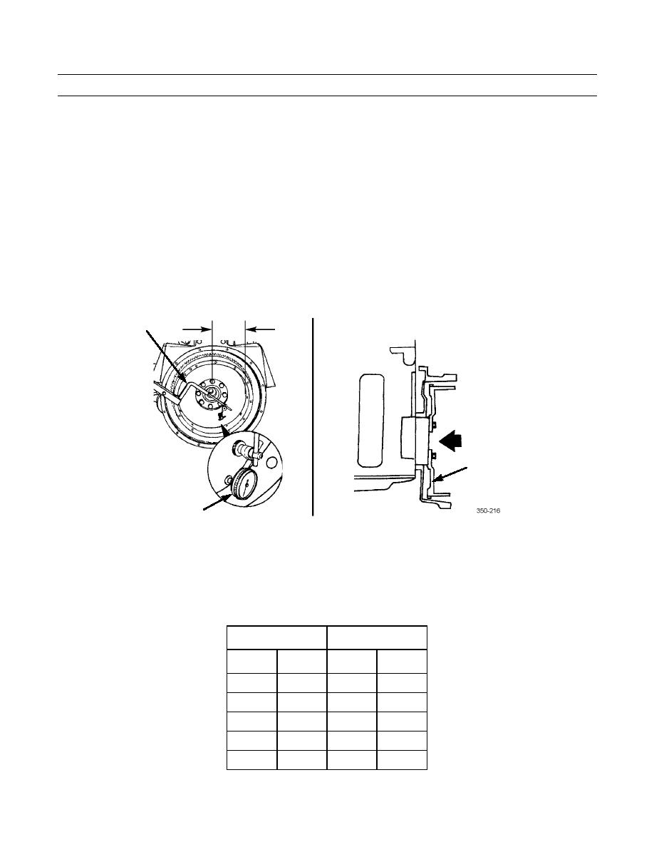
Measure flywheel face runout as follows:
a.
Install dial indicator (8) and attachments (7).
b.
Push flywheel (4) forward to remove crankshaft end thrust.
A
7
4
8
Zero and position dial indicator at radius indicated in Table 1, Flywheel Face Runout.
c.
d.
Rotate crankshaft, using engine barring tool, one revolution and record total indicator reading.
Repeat steps a thru d for each radius setting listed in Table 1, Flywheel Face Runout.
e.
Table 1. Flywheel Face Runout.
RADIUS (A)
MAXIMUM TIR
MM
IN.
MM
IN.
203
8
0.203
0.008
254
10
0.254
0.010
305
12
0.305
0.012
356
14
0.356
0.014
406
16
0.406
0.016
0204 00-4


