TM 10-3930-675-24-2
VALVE AND INJECTOR ADJUSTMENTS - CONTINUED
0207 00
VALVE LASH CHECK - CONTINUED
3.
Observe rocker lever arms of cylinder and compare rocker lever arm positions to Table 1. Intake and exhaust valves
must be closed and injector plunger must be at bottom of stroke for cylinder 1. If this is not correct, cylinder 6 must be
ready to check.
Table 1. Injector and Valve Measurement Sequence.
BAR ENGINE IN
SET CYLINDER
DIRECTION OF
PULLEY POSITION
INJECTOR
VALVE
ROTATION
Start
A
1
1
Advance to
B
5
5
Advance to
C
3
3
Advance to
A
6
6
Advance to
B
2
2
Advance to
C
4
4
Firing Order: 1-5-3-6-2-4
NOTE
Ensure rocker levers on both intake and exhaust valves of cylinder being checked can be "rattled" or
push tubes can be freely rotated.
4.
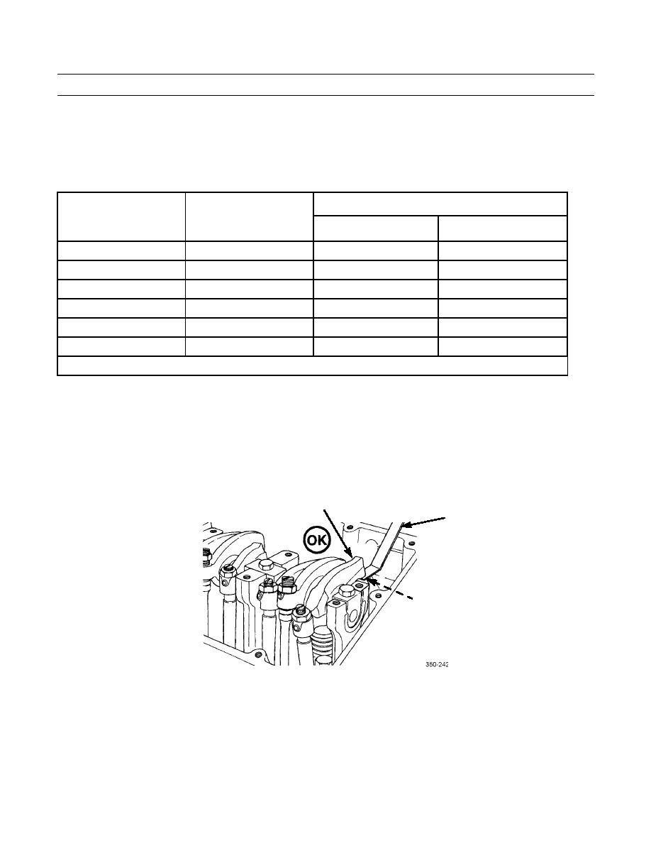
With thickness gage, measure and record amount of clearance between crosshead and rocker lever nose for both intake
and exhaust valve.
ROCKER
LEVER NOSE
THICKNESS
GAGE
CROSSHEAD
0207 00-3


