TM 10-3930-675-24-2
VALVE AND INJECTOR ADJUSTMENTS - CONTINUED
0207 00
INJECTOR ADJUSTMENT - CONTINUED
1.
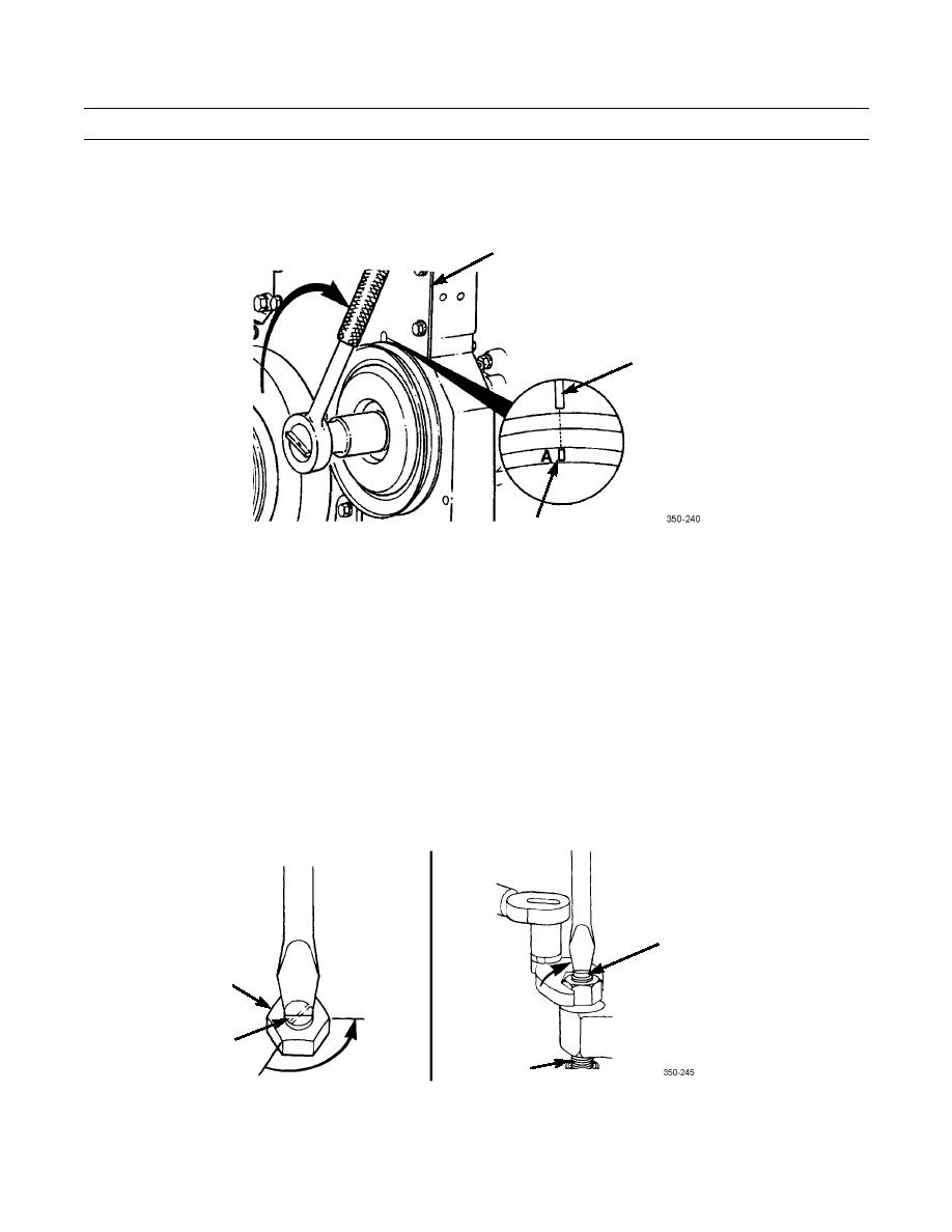
Rotate accessory drive clockwise until "A" valve set mark on accessory drive pulley is aligned with pointer on gear
cover.
GEAR COVER
GEAR COVER
POINTER
VALVE
SET MARK
2.
With valve set mark "A" aligned with pointer, observe both valve rocker levers for cylinder 1. Intake and exhaust valves
for cylinder must be closed. If condition is not met, then cylinder 6 injector and valves must be ready to set.
3.
Adjust injector as follows:
a.
Loosen injector adjusting screw locknut.
b.
Bottom injector plunger three or four times to remove fuel.
NOTE
DO NOT use excessive force when bottoming plunger.
c.
Turn adjusting screw in until you can feel it lightly bottom plunger.
d.
Back out adjusting screw two flats or 120 degrees.
e.
Hold adjusting screw and tighten locknut to 45 lb-ft (61 Nm).
ADJUSTING
SCREW
LOCKNUT
ADJUSTING
SCREW
120
INJECTOR
PLUNGER
4.
Perform valve adjustments on same cylinder.
0207 00-6


