
TM 10-3930-675-24-2
TOPHANDLER WIRING HARNESSES REPLACEMENT - CONTINUED
0221 00
WIRING HARNESS D, JUNCTION BOX 182-TO-JUNCTION BOX 183: REMOVAL - CONTINUED
6.
Remove retainer nut (30), grommet (31), and sleeve (32).
NOTE
Use wiring diagrams in WP 0048 00, as needed, and note terminal block numbers to wire lead num-
bers for installation.
7.
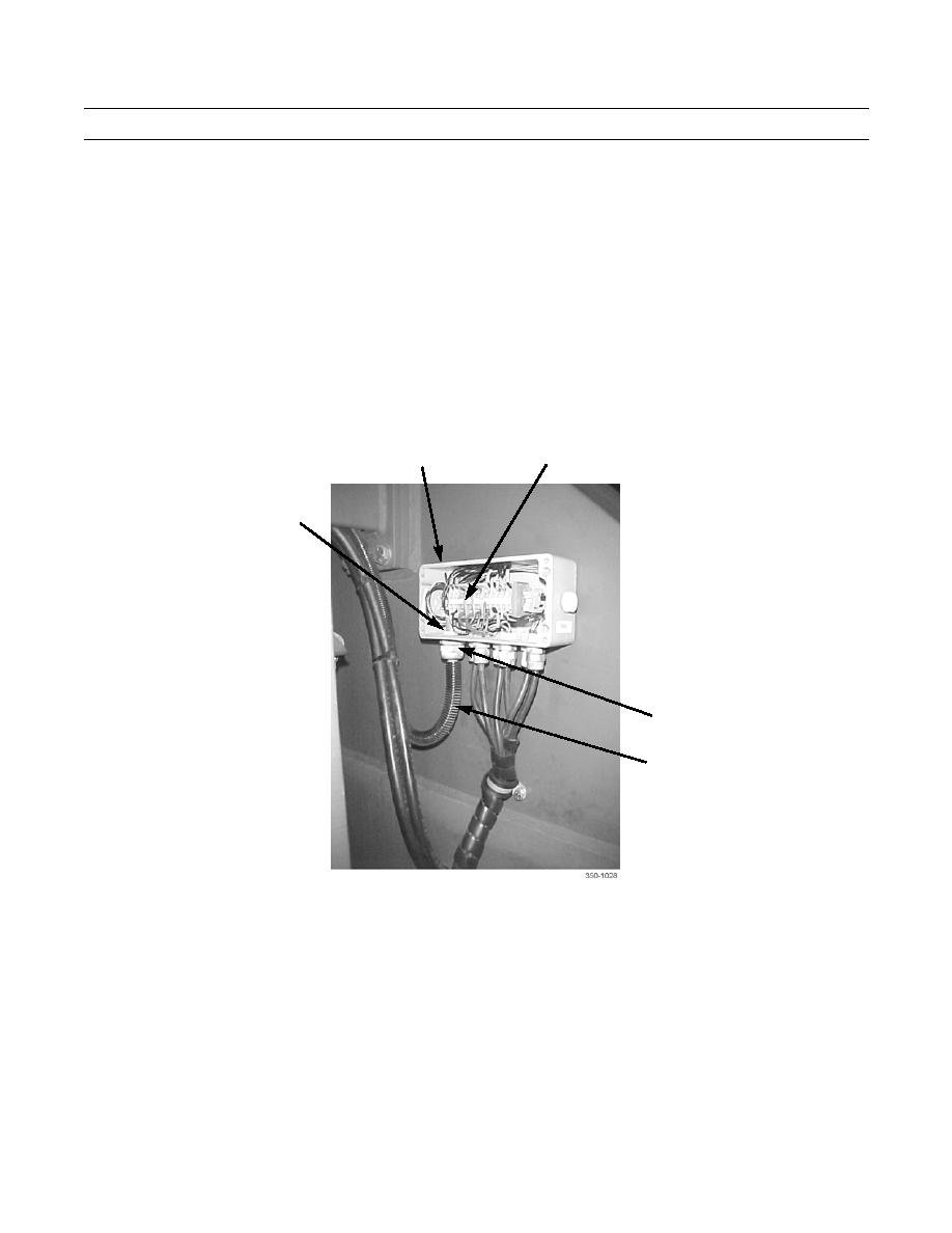
Using jeweler's screwdriver, disconnect wiring harness D (25) leads from junction box 183 (28) terminal block (29).
Remove harness from junction box.
8.
Remove wiring harness D (25) from cable guard (33) along cable routing. Retain cable guard.
28
29
25
30,31,32
33
WIRING HARNESS D, JUNCTION BOX 182-TO-JUNCTION BOX 183: INSTALLATION
1.
Install wiring harness D (25) through cable guard (33) and position wiring harness along cable routing.
2.
Position retainer nut (30), grommet (31), and sleeve (32) on wiring harness D (25) at junction box 183 (28). Install har-
ness into junction box.
3.
Using jeweler's screwdriver, connect wiring harness D (25) leads to terminal block (29).
4.
Install sleeve (32), grommet (31), and retainer nut (30).
5.
Install cover (26) on junction box 183 (28) and tighten four screws (27).
0221 00-12
