
TM 5-3810-306-34
d. After assembly, hit valve stems with a plastic
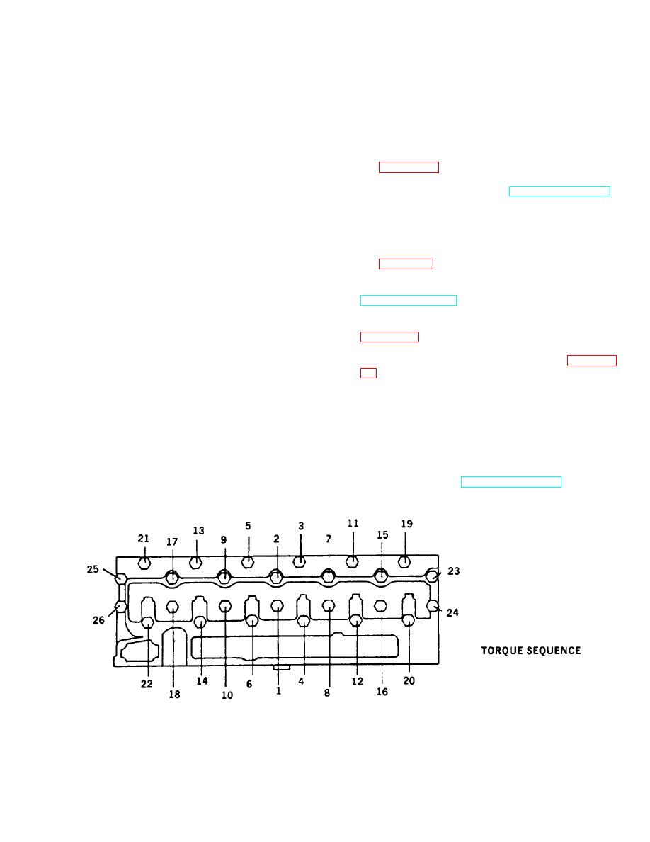
d. Torque capscrews (2) and (3) first time to 27 ft-
hammer to ensure valve spring locks (5) are
lbs (36 Nm) in sequence shown. Repeat in
seated.
same sequence to torque of 110 ft-lbs (146 Nm).
Finally torque capscrews in same sequence to
148 ft-lbs (197 Nm).
INSTALLATION:
2. INSTALL ROCKER LEVER ASSEMBLIES. (REFER
1. INSTALL CYLINDER HEAD (1).
TO PAGE 4-53.)
a. Position new gasket (4) onto cylinder block
3. ADJUST VALVES. (REFER TO TM 5-3810-306-20.)
dowels.
4. INSTALL VALVE COVER. (REFER TO TM 5-3810-
NOTE
306-20.)
Cylinder block and cylinder head
5. INSTALL FUEL INJECTORS AND LINES. (REFER
must be clean and dry.
TO PAGE 5-2.)
b. Carefully place cylinder head (1) onto gasket (4)
6. INSTALL THERMOSTAT HOUSING. (REFER TO
on cylinder block. Make sure cylinder head (1) is
TM 5-3810-306-20.)
aligned on dowels.
7. INSTALL EXHAUST MANIFOLD.
(REFER TO
CAUTION
Do not install capscrews with painted
8. INSTALL TURBOCHARGER. (REFER TO PAGE 5-
heads in the center rows which will
be covered by the valve cover.
9. INSTALL ENGINE HOOD. (REFER TO TM 5-3810-
c.
Install lubricated cylinder head capscrews (2)
306-20.)
and (3).
10. SERVICE RADIATOR. (REFER TO LO 5-3810-306-
12.)
11. CONNECT NEGATIVE BATTERY CABLE
AT
SHUNT. (REFER TO TM 5-3810-306-20.)
END OF TASK
4-18
