
TM 5-3810-306-34
ASSEMBLY:
1. ASSEMBLE ALTERNATOR.
g. Install strap (11) and secure one end to
housing using nut (12) and attaching
hardware.
CAUTION
h. Install stator (10), stator leads (8) and nuts
Be certain slip ring end frame is clean
(7).
prior to assembly.
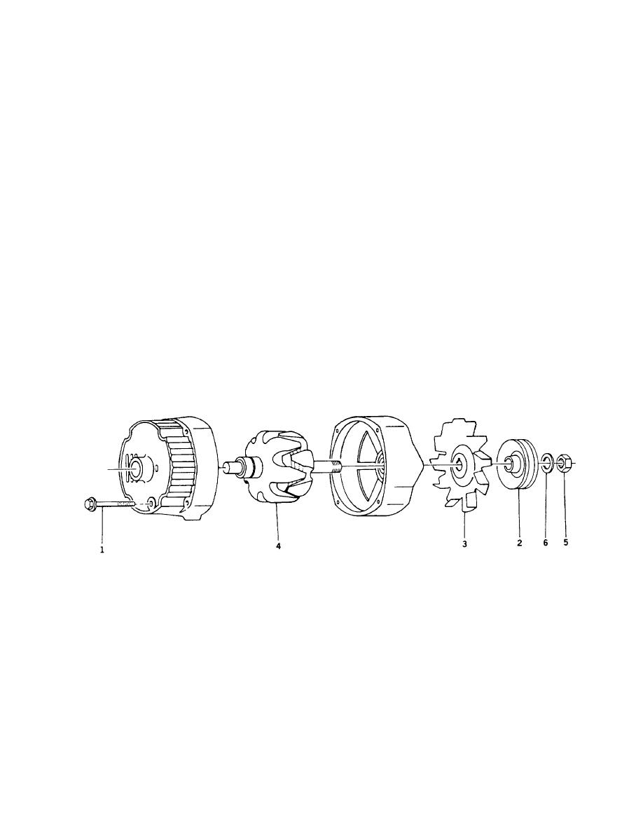
i. If removed, install rotor (4), fan (3), pulley
a. Install battery terminal strap (25) and
(2), washer (6), and nut (5). Torque nut
secure one end with nut (24) and attaching
(5) to 70-80 ft-lbs (95-108 Nm).
hardware.
NOTE
b. Install capacitor (23), rectifier assembly (9)
(Under end of battery terminal strap (25)
Make sure rotor (4) shaft is clean.
and one end of wire (21). Secure all four
Insert pin through hole in end frame
items using four screws (22).
to hold brushes and springs up in
c. Install regulator (18) and other end of wire
brush holder during assembly.
(21) and secure both with nut (20).
Remove pin after thrubolts (1) are
tightened to allow brushes to contact
d. Install brushes (19) in brush holder (17).
slip rings.
e. Install brush holder (17), insulated screw
j. Assembly slip ring end frame to drive end
(15) and ground screw (16).
frame. Align scribe mark on frames and
install thrubolts (1).
f. Install diode (14) and insulated screw (13).
6-6
